
Split mechanism for a coaxial photographing device

a photographing device and coaxial technology, applied in the field of splitting mechanism of coaxial photographing device, can solve the problems of long adjustment work, long adjustment work, and repetitive, and achieve the effect of dissipating waste heat and preventing dust staining

Inactive Publication Date: 2011-02-01
HUANG I HSIN
View PDF5 Cites 6 Cited by
  • Summary
  • Abstract
  • Description
  • Claims
  • Application Information

AI Technical Summary

Benefits of technology

"The present invention provides a split mechanism for a coaxial photographing device that facilitates calibration and maintenance. The split mechanism allows for an axial straight splitting between the photographing unit and the light projection unit, which can be offset from the axis and maintain a full operation. The light projection unit can emit a light beam that is parallel to the image wave of the photographing unit to provide image adjustment operation aided by infrared. The split mechanism is safe and prevents damage to the device when disassembling or scattering the light projection unit. The light projection unit can be fully disassembled to facilitate exchanging the lens. The split mechanism also provides an operational space, prevents unnecessary light interference, and dissipates waste heat rapidly. The light projection unit and the photographing unit are locked by an annular locking element that provides a water-proofing function and effectively seals the device for use in water."

Problems solved by technology

However, the adjustment value is not in compliance with a nighttime auxiliary light source, as in particular, invisible infrared is emitted by the light projection module 92 at the nighttime to prevent to visible light from affecting people, events and objects.
The conventional photographing device is provided with following shortcomings:1. As the light projection module will be scattered after being disassembled by the high sky operation, it will result in a danger.2. As two adjustment persons are usually required to operate at a same time, a manpower loading and a danger of high sky cooperation will be increased.3. Upon reassembling after adjustment, a rim of the through-hole of the light projection module will hit the lens, which may allow the lens to be shifted or damaged.4. If the exterior of the device is further protected by a protection lens, then an interior surface of the protection lens will reflect a scattered wave of the infrared to enter into the lens, thereby affecting the photographing condition of the lens.5. When adjusting, as the auxiliary light is held by a bare hand, a swinging will be resulted.
If the object to be photographed is there-dimensional, then reflection brilliance is at a left, right, upper or lower side of the object will be changed due to the swinging, allowing the adjustment work to be lengthy and repetitive, which is one of major obstacles in the adjustment operation.
Therefore, the adjustment work will take a substantial percentage in installation cost.

Method used


Image

  • Split mechanism for a coaxial photographing device
  • Split mechanism for a coaxial photographing device
  • Split mechanism for a coaxial photographing device

Examples


Embodiment Construction

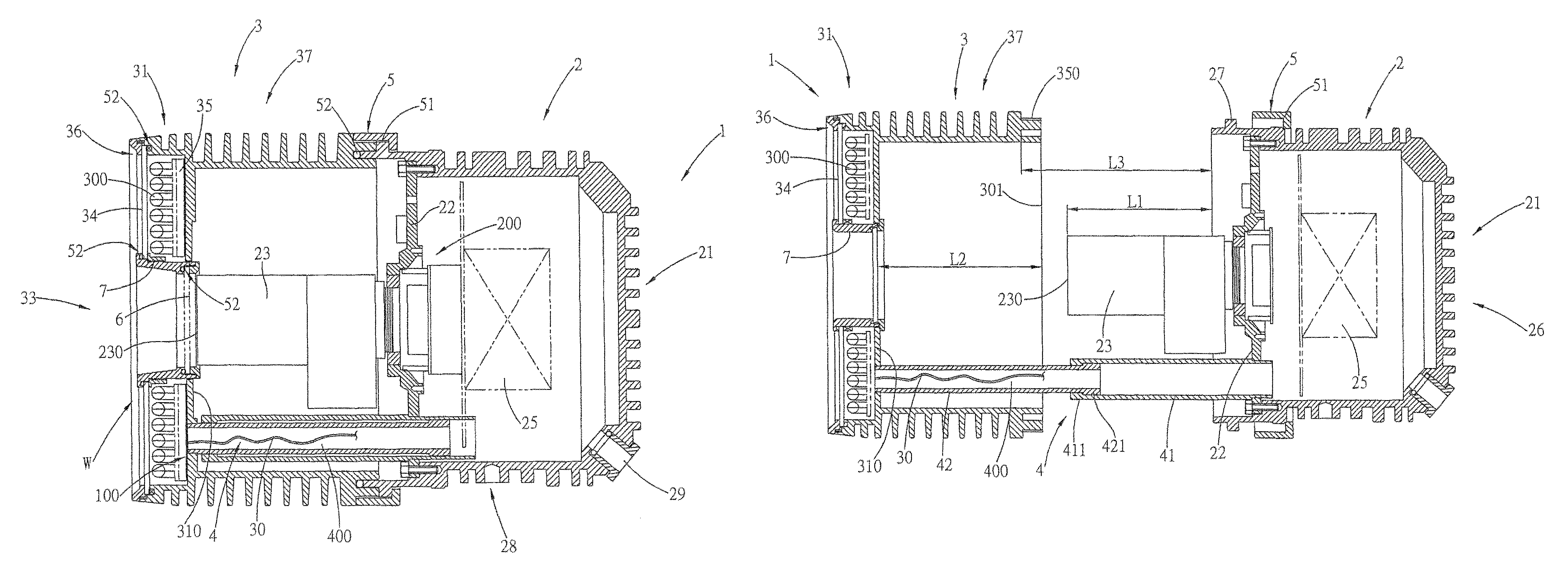
[0035]Referring to FIG. 1, a photographing device 1 is constituted primarily by a photographing unit 2 which is coaxially assembled with a light projection unit 3 (the definition of co-axis is that an axis of an image wave is overlapped with an axis of a light beam emitted from the light projection unit 3). The photographing unit 2 is enclosed by a cup-shape housing 21, an interior of which is installed with a photographing module 200 that is linked indirectly with the cup-shape housing 21 through a substrate 22, and is provided with an electronic driving device 25 that instructs an electric operation of the photographing module 200 and a light emitting module 300. The electronic driving device 25 conducts electricity and a two-way signal through a cable from a connection hole 29, and an exterior is provided with a linking par 28 which is assembled on a bracket (not shown in the drawing) by any fixing method.

[0036]The light projection unit 3 is assembled by a cylindrical housing 31,...


PUM


Abstract

A split mechanism for a coaxial photographing device, especially a split mechanism between a photographing unit and a light projection unit of a photographing device used for a full-time surveillance to facilitate an image adjustment or maintenance, uses primarily the photographing unit as a base of support, with the removable light projection unit being assembled coaxially at an image taking end. After the light projection unit is disassembled and changes a position, it can be linked at a constant direction temporarily and can keep operating by using a linking device which is split linearly, such that a calibration light wave needed for adjusting the images can be provided, and the light projection unit can be easily aligned with an axis to be assembled at position upon assembling.

Description

BACKGROUND OF THE INVENTION[0001]a) Field of the Invention[0002]The present invention relates to a split mechanism for a coaxial photographing device, and more particular to a split, assembly and disassembly mechanism between a photographing unit and a light projection unit of a photographing device used for a full-time surveillance.[0003]b) Description of the Prior Art[0004]A coaxial photographing device is used in a surveillance system, wherein an auxiliary light source is provided in a night projection to serve as a photographing device for a full-time surveillance, with an optic axis along which images are coming into the device same as an optic axis along which light is projecting.[0005]Referring to FIG. 9, a photographing device 9 includes primarily a light projection module 92 which is coaxially attached with a photographing module 91 with a same optic axis S, wherein lens 910 is transfixed through a central through-hole 95 of the light projection module 92 to be attached coa...

Claims


Application Information

Patent Timeline
Patent Type & Authority Patents(United States)
IPC IPC(8): G03B17/04G03B17/02
CPCG03B15/03
Inventor HUANG, I-HSIN
Owner HUANG I HSIN
Learn More