
Method and apparatus for surface processing of a substrate

a substrate and surface technology, applied in the field of material processing, can solve the problems of reducing the area over which lift-off is acceptable, and reducing the uniformity of magnetic properties

Active Publication Date: 2011-02-01
VEECO INSTR
View PDF20 Cites 15 Cited by
  • Summary
  • Abstract
  • Description
  • Claims
  • Application Information

AI Technical Summary

Benefits of technology

The invention is a system and method for processing a substrate by using a beam of energetic particles. The system includes a vacuum chamber, a source, a fixture, and a shield. The fixture holds the substrate in the vacuum chamber and translates it in a plane parallel to the source. The shield has a rectangular aperture that transmits the beam over a treatment area on the substrate. The method involves aligning parallel features on the substrate with the aperture and exposing it to the beam. The substrate can also be rotated to process both sides of the feature. The technical effects of the invention include improved processing precision and efficiency.

Problems solved by technology

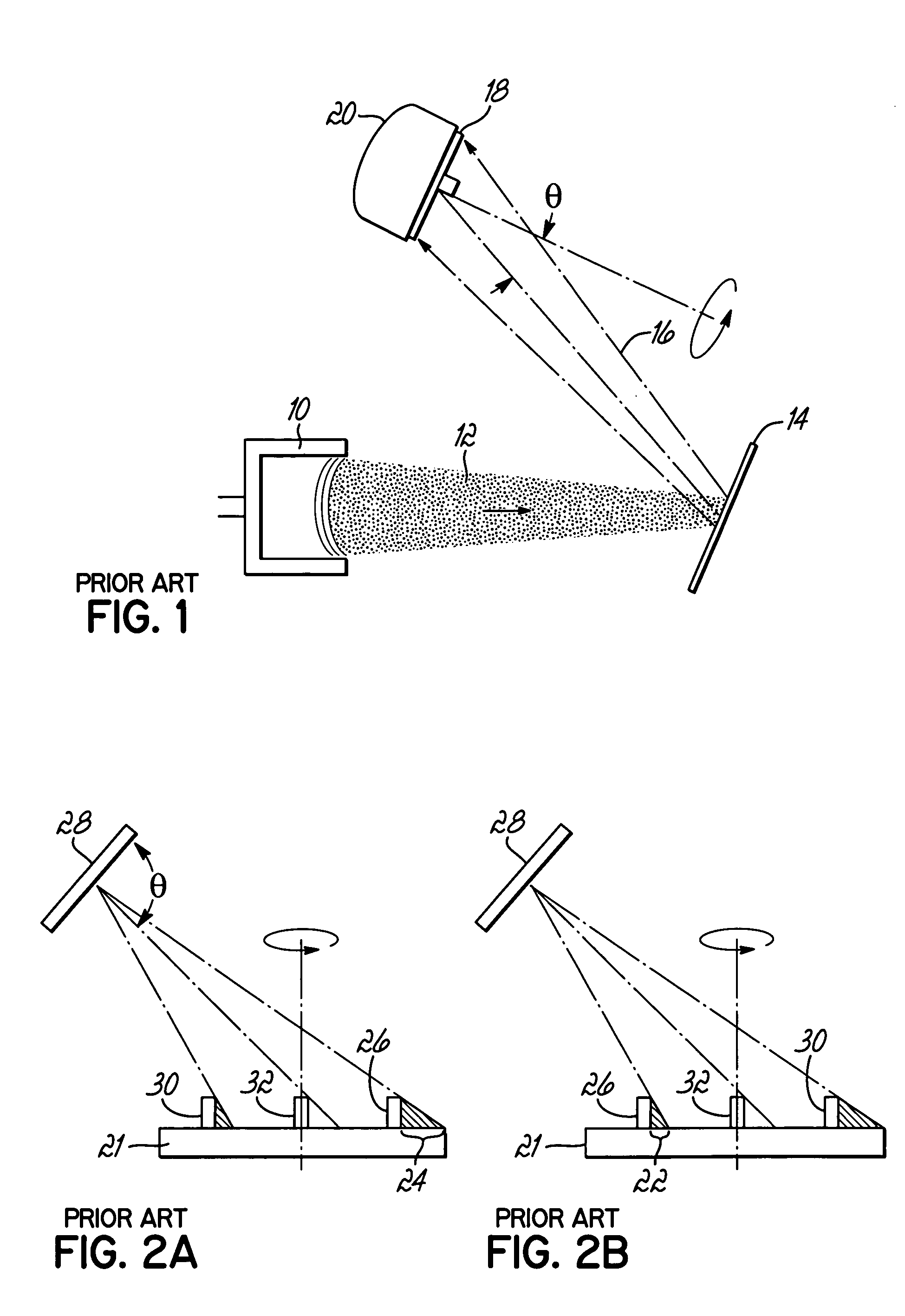
This causes the deposited material to have an asymmetric deposition profile relative to the features, which reduces the area over which lift-off is acceptable and reduces magnetic property uniformity.

Method used


Image

  • Method and apparatus for surface processing of a substrate
  • Method and apparatus for surface processing of a substrate
  • Method and apparatus for surface processing of a substrate

Examples


Embodiment Construction

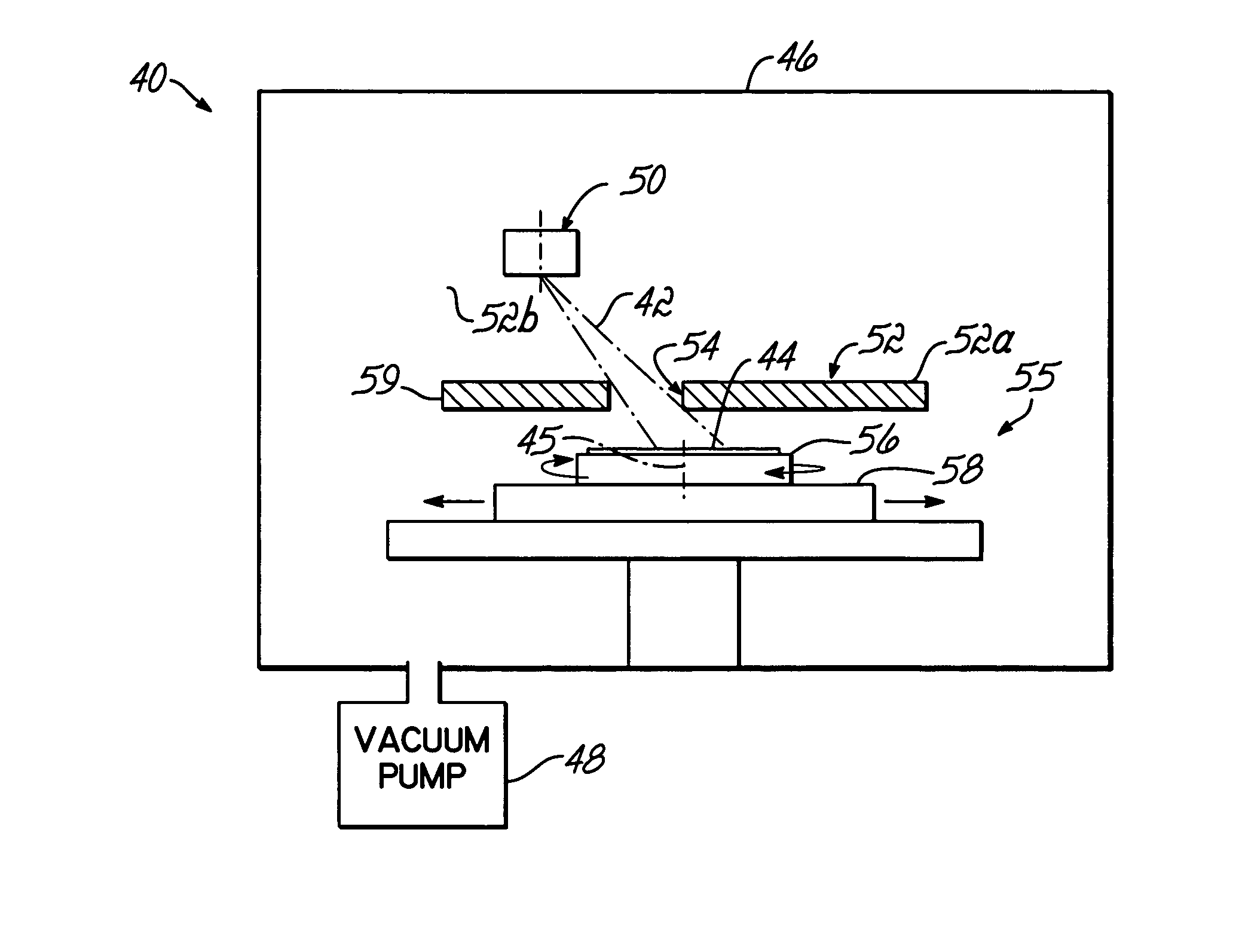
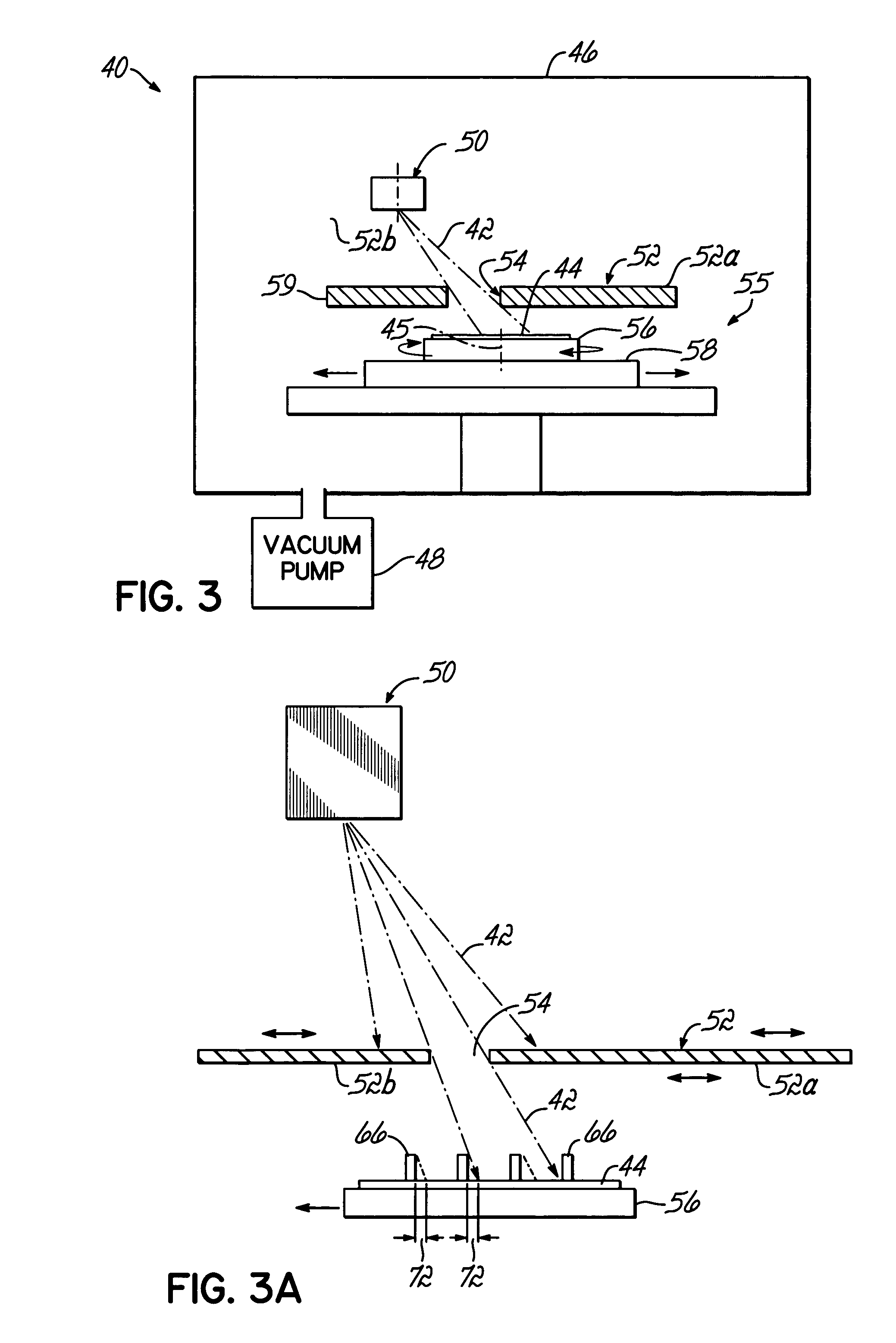
[0039]With reference to FIGS. 3 and 3A, a processing apparatus 40 includes a source 50, which is preferably rectangular but not so limited, adapted to emit a beam 42 of energetic particles. The energetic particles from source 50 may etch a substrate 44, deposit a thin film or layer of material on substrate 44, or otherwise treat substrate 44. The source 50 may have a geometrical shape similar to the geometrical shape of aperture 54, which reduces the unused portion of the beam 42 from the source 50 that does not treat the substrate 44. The source 50 is characterized by a major dimension 49 (FIG. 4A) and a minor dimension 51 (FIG. 4A). Beam 42 has a substantially uniform flux distribution along the major dimension 49 of the source 50.

[0040]The apparatus 40 includes a vacuum chamber 46 that is isolated from the surrounding environment. Vacuum chamber 46 may be evacuated to a suitable vacuum pressure by a vacuum pump 48 as recognized by a person of ordinary skill in the art. A sealable...


PUM

PropertyMeasurementUnit
dimensionaaaaaaaaaa
collimation angleaaaaaaaaaa
incident angleaaaaaaaaaa

Abstract

Method and apparatus for processing a substrate with a beam of energetic particles. The beam is directed from a source through a rectangular aperture in a shield positioned between the source and substrate to a treatment zone in a plane of substrate movement. Features on the substrate are aligned parallel to a major dimension of the rectangular aperture and the substrate is moved orthogonally to the aperture's major dimension. The beam impinges the substrate through the aperture during movement. The substrate may be periodically rotated by approximately 180° to reorient the features relative to the major dimension of the rectangular aperture. The resulting treatment profile is symmetrical about the sides of the features oriented toward the major dimension of the rectangular aperture.

Description

CROSS REFERENCE TO RELATED APPLICATIONS[0001]The present application claims benefit of U.S. Provisional Application Ser. No. 60 / 494,281, filed Aug. 11, 2003, the disclosure of which is hereby incorporated herein by reference in its entirety.FIELD OF THE INVENTION[0002]This invention relates generally to materials processing and, more particularly, to apparatus and methods for processing or treating the surface of a substrate with a beam of energetic particles.BACKGROUND OF THE INVENTION[0003]Sputter deposition and ion beam deposition (IBD) are familiar methods for depositing thin film materials. These deposition processes require deposition on substrates with particular topographical features that affect the distribution and properties of deposited material across the substrate. For example, lift-off deposition processes in which thin films are deposited over a pattern of photoresist features are used in many important thin film device fabrication processes.[0004]IBD is particularly...

Claims


Application Information

Patent Timeline
Patent Type & Authority Patents(United States)
IPC IPC(8): C23C14/00C23C14/32C25B9/00C25B13/00C25B11/00C23C14/04C23C14/22C23C16/00
CPCC23C14/044C23C14/221
Inventor DRUZ, BORISKANAROV, VIKTORHEGDE, HARIHARAKESHAVE S.HAYES, ALAN V.LAKIOS, EMMANUEL
Owner VEECO INSTR
Learn More