Surface emitting laser

a laser and surface technology, applied in the field of surface emitting lasers, can solve the problems of low current injection efficiency, insufficient carrier injection to reach the active layer, and difficult to obtain a high laser beam output, etc., to achieve high power, suppress light absorption, and high efficiency of current injection

Inactive Publication Date: 2011-01-25
CANON KK
View PDF7 Cites 6 Cited by
  • Summary
  • Abstract
  • Description
  • Claims
  • Application Information

AI Technical Summary

Benefits of technology

[0025]The surface emitting laser according to the present invention enables suppression of light absorption as well as highly efficient current injection into an active layer to attain a high power.

Problems solved by technology

However, the surface emitting lasers of conventional examples disclosed in Japanese Patent Application Laid-Open No. 2003-273453 and U.S. Pat. No. 6,154,480 have following problem in attaining a high power.
As a result, there occurs a disadvantage that carrier injection is not performed fully enough to reach an active layer.
Accordingly, current injection efficiency drops, which makes it difficult to obtain a high laser beam output.
Thus, a high laser beam output is difficult to obtain.

Method used


Image

  • Surface emitting laser
  • Surface emitting laser
  • Surface emitting laser

Examples


embodiment

[0054]Referring now to accompanying drawings, description will be made on an embodiment of the present invention.

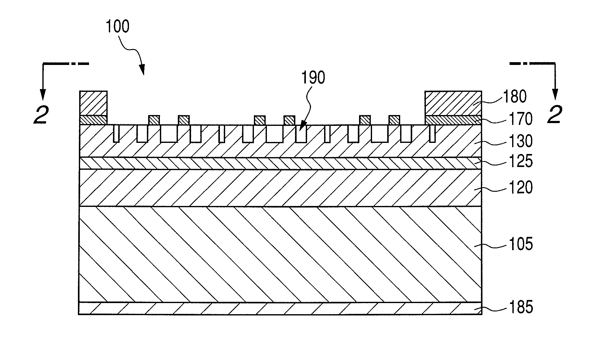
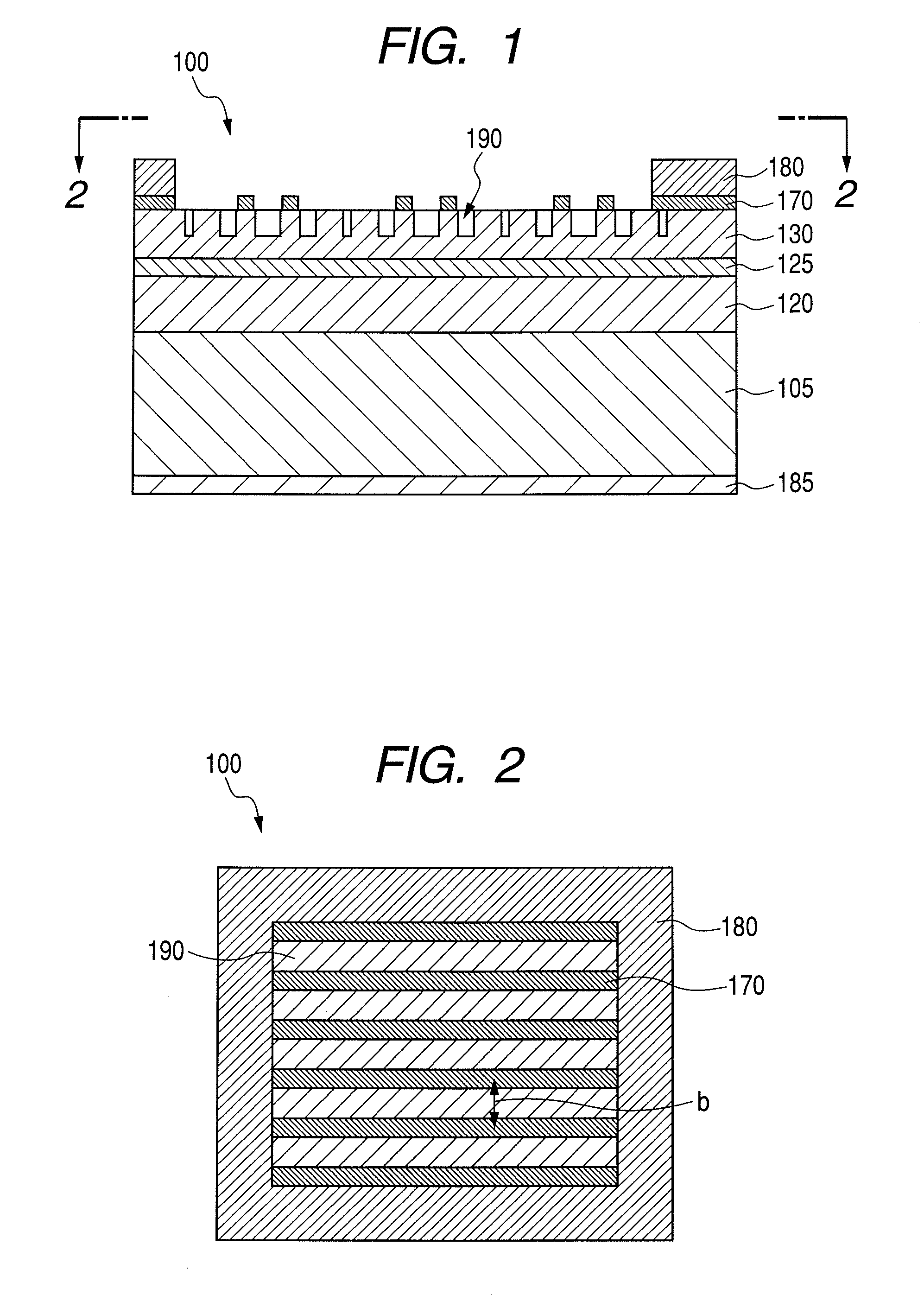
[0055]FIG. 1 illustrates a sectional schematic view illustrating a surface emitting laser in the present embodiment.

[0056]FIG. 2 is a top schematic view of the surface emitting laser in FIG. 1.

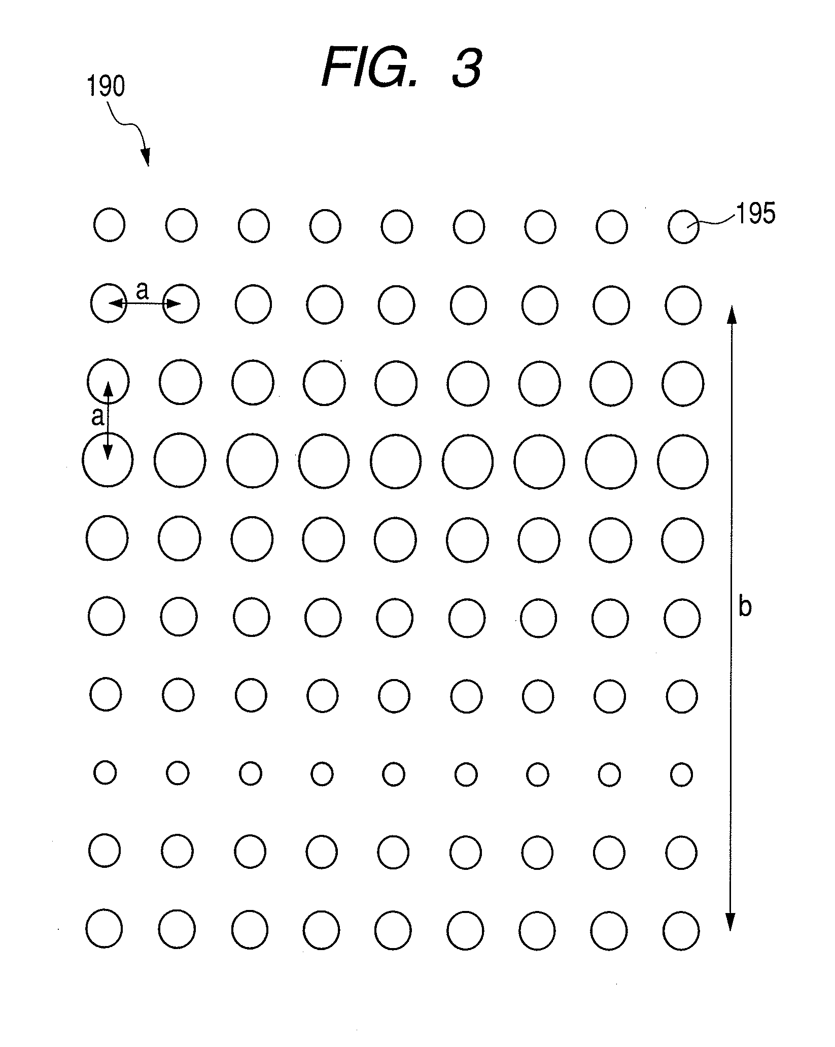
[0057]In FIGS. 1 and 2, reference numeral 100 denotes a surface emitting laser, reference numeral 105 denotes a substrate, reference numeral 120 denotes a lower clad layer, reference numeral 125 denotes an active layer, reference numeral 130 denotes an upper clad layer, reference numeral 170 denotes a conductive film, reference numeral 180 denotes an upper electrode, reference numeral 185 denotes a lower electrode and reference numeral 190 denotes a photonic crystal structure.

[0058]As illustrated in FIG. 1, the surface emitting laser 100 in the present embodiment has the lower clad layer 120, the active layer 125 and the upper clad layer 130 on the substrate 105.

[0059]The upper clad...


PUM


Abstract

A surface emitting laser having a photonic crystal layer 130 on a substrate 105 with an active layer therebetween, in which the photonic crystal layer includes at least a first periodic structure for resonating in an in-plane direction and a second periodic structure for modulating a light intensity distribution in an in-plane direction. The light intensity in the photonic crystal layer is periodically distributed to a region having high light intensity and a region having low light intensity by the second periodic structure. Further, a conductive film 170 for performing current injection into the active layer is selectively provided just above the region having low light intensity. The surface emitting laser provides suppression of light absorption and highly efficient current injection into an active layer to attain a high power.

Description

BACKGROUND OF THE INVENTION[0001]1. Field of the Invention[0002]The present invention relates to a surface emitting laser and, in particular, to a high-power surface emitting laser.[0003]2. Description of the Related Art[0004]Recent attention has focused on a surface emitting laser as a light source for optical communication, optical transmission or electrophotography.[0005]The surface emitting laser has excellent characteristics such as a single longitudinal mode, a low threshold and easy two-dimensional array formation.[0006]For such a surface emitting laser, development of two-dimensional photonic crystal surface emitting laser utilizing a photonic crystal has been accelerated.[0007]The photonic crystal used herein is a structure having a refractive index period equal to or smaller than the wavelength of light.[0008]A two-dimensional photonic crystal surface emitting laser as disclosed in Japanese Patent Application Laid-Open No. 2003-273453 has a photonic crystal periodic struct...

Claims


Application Information

Patent Timeline
Patent Type & Authority Patents(United States)
IPC IPC(8): H01S5/00H01S5/185
CPCH01S5/18H01S5/0425H01S5/105H01S5/04254H01S5/04253H01S5/11H01S5/185
Inventor IKUTA, MITSUHIRO
Owner CANON KK
Why Eureka
Try Eureka