
Method for manufacturing a thermopile on a membrane and a membrane-less thermopile, the thermopile thus obtained and a thermoelectric generator comprising such thermopiles

Inactive Publication Date: 2011-01-25
STICHTING IMEC NEDERLAND
View PDF30 Cites 39 Cited by
  • Summary
  • Abstract
  • Description
  • Claims
  • Application Information

AI Technical Summary

Benefits of technology

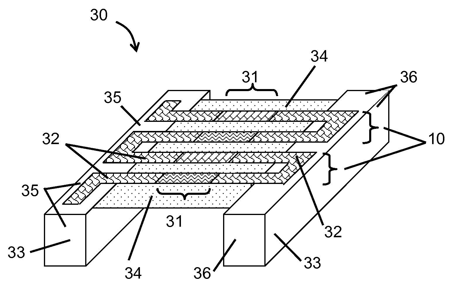
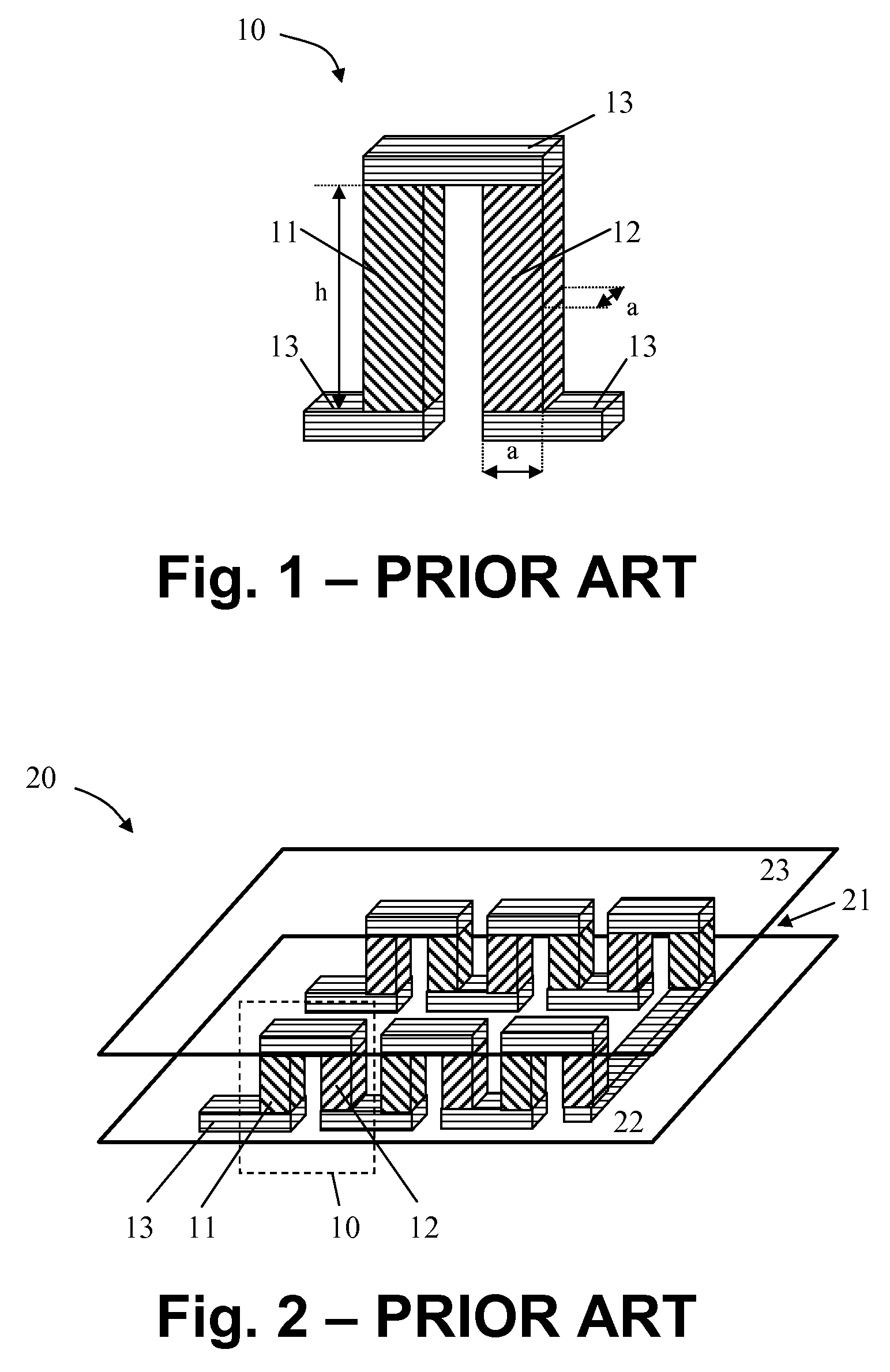
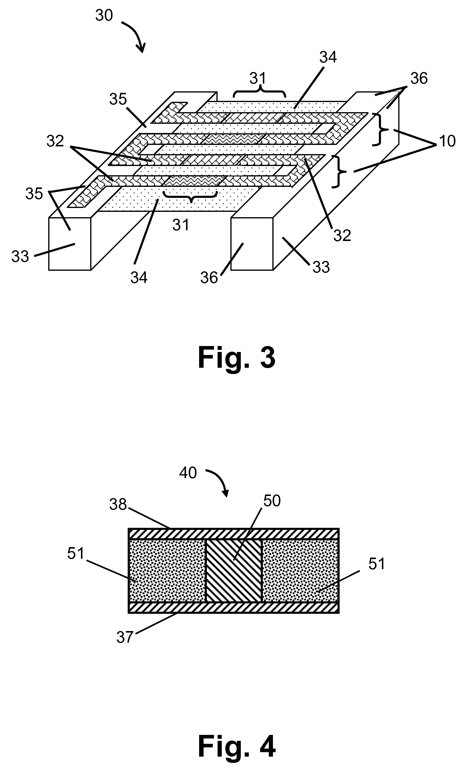
It is an object of the present disclosure to provide a method for manufacturing good thermopile chips, thermopile units and TEGs with such thermopile chips for applications on a heat source and / or on a heat sink with high thermal resistance. Thermopiles manufactured according to the present disclosure comprise thermocouples that may be supported by a membrane layer or that may be self-supporting. The thermocouples may have dimensions so as to be flexible, e.g. bendable. Due to this flexibility, the thermocouples may be shock absorbing, leading to a lower risk of damage to the thermocouples as compared to prior art devices, e.g. micromachined devices. The thermocouple legs of thermopile chips according to the present disclosure may be wider and / or longer than in prior art devices, leading to a cheaper technology being available for manufacturing such thermocouple legs. Moreover, better and more reliable electrical contacts may be obtained in thermopile chips according to the present disclosure. Thermopile chips according to the present disclosure may have a reduced sensitivity to dust during manufacturing as compared to prior art methods. Therefore the method for manufacturing thermopile ships according to the present disclosure may have a good manufacturing yield. Furthermore, a good quality of thermoelectric material may be obtained and both types of thermoelectric material may be optimised independently.
According to the present disclosure, electrically connecting the plurality of first type thermocouple legs with a plurality of second type thermocouple legs may comprise providing on the first surface of the first substrate a plurality of second type thermocouple legs, wherein the plurality of second type thermocouple legs are attached between the first hot carrier part and the first cold carrier part. Alternatively, according to the present disclosure, electrically connecting the plurality of first thermocouple legs with a plurality of second type thermocouple legs may comprise: providing on a first surface of a second substrate a plurality of second type thermocouple legs and thereafter forming a second carrier frame from the second substrate by removing part of the second substrate form a second surface opposite to the first surface, the second carrier frame comprising a second hot carrier part, a second cold carrier part and second removable beams, thus at least partially releasing the second type thermocouple legs from the second substrate, the second type thermocouple legs being attached between the second hot carrier part and the second cold carrier part. It is an advantage of providing the first type thermocouple legs on a first substrate and the second type thermocouple legs on a second substrate that the quality of both types of thermocouple legs may be improved or even optimised independently.

Problems solved by technology

Due to this flexibility, the thermocouples may be shock absorbing, leading to a lower risk of damage to the thermocouples as compared to prior art devices, e.g. micromachined devices.

Method used


Image

  • Method for manufacturing a thermopile on a membrane and a membrane-less thermopile, the thermopile thus obtained and a thermoelectric generator comprising such thermopiles
  • Method for manufacturing a thermopile on a membrane and a membrane-less thermopile, the thermopile thus obtained and a thermoelectric generator comprising such thermopiles
  • Method for manufacturing a thermopile on a membrane and a membrane-less thermopile, the thermopile thus obtained and a thermoelectric generator comprising such thermopiles

Examples


case 1

t thermal shunts (FIG. 13). A 3 μm thick film of BiTe is used for forming the layers of thermoelectric material. In the TEG, 14 thermopile chips are coupled into 7 couples in a way similar to the one shown in FIG. 20, face to face on a couple by couple basis. A good electrical contact resistance of 10Ω·μm2 between the interconnection metal and the thermoelectric material is assumed. The dependence of the power produced by the TEG on the length of the thermocouple legs (or on a membrane length which is the same in the case considered here) at such conditions is shown in FIG. 34.

case 2

t thermal shunts (FIG. 13). A 1 μm thin film of BiTe is considered, to obtain a 3-fold decrease of the film deposition time as compared to Case 1. In the TEG, 10 thermopile chips are coupled into 5 couples in a way similar to the one shown in FIG. 20, face to face on a couple by couple basis. As compared to Case 1, this results in a decrease of the production cost per TEG. A moderately good electrical contact resistance of 100Ω·μm2 between the interconnection metal and the thermoelectric material is assumed. The dependence of the power produced by the TEG on the length of the thermocouple legs (or on the membrane length which is the same in the case considered here) at such conditions is shown in FIG. 35.

case 3

hermal shunts (FIG. 22). In this case the length of the thermocouple legs is less than the length of the membrane. A 3 μm thick film of BiTe is used for forming the layers of thermoelectric material. The TEG comprises 14 thermopile chips and a contact resistance of 10Ω·μm2 between the interconnection metal and the thermoelectric material is assumed, as in Case 1. The dependence of the power produced by the TEG on the length of a membrane is shown in FIG. 36 for a 0.5 mm-long thermocouple leg. The dependence of the power produced by a TEG with a 3.8 mm-long membrane on the length of the thermocouple legs is shown in FIG. 37.


PUM


Abstract

A method for manufacturing thermopile carrier chips comprises forming first type thermocouple legs and second type thermocouple legs on a first surface of a substrate and afterwards removing part of the substrate form a second surface opposite to the first surface, thereby forming a carrier frame from the substrate and at least partially releasing the thermocouple legs from the substrate, wherein the thermocouple legs are attached between parts of the carrier frame. First type thermocouple legs and second type thermocouple legs may be formed on the same substrate or on a separate substrate. In the latter approach both types of thermocouple legs may be optimised independently. The thermocouple legs may be self-supporting or they may be supported by a thin membrane layer. After mounting the thermopile carrier chips in a thermopile unit or in a thermoelectric generator, the sides of the carrier frame to which no thermocouple legs are attached are removed. A thermoelectric generator according to the present disclosure may be used for generating electrical power, for example for powering an electrical device such as a watch. It may be used with a heat source and / or heat sink with high thermal resistance, such as a human body.

Description

TECHNICAL FIELDThe present disclosure relates to thermopiles and to thermoelectric generators (TEGs) for scavenging of ambient energy, and more specifically to TEGs operated with a heat source and / or with a heat sink having a large thermal resistance, e.g. to TEGs operated under conditions of non-constant heat flow and non-constant temperature difference. The disclosure also relates to a method of manufacturing thermopiles suited for applications on a heat source or a heat sink with high thermal resistance, e.g. on a human body or on a body of any other endotherm. The disclosure furthermore relates to applications where a TEG dissipates heat into a fluid with high thermal resistance such as for example air or receives heat from a fluid with high thermal resistance such as for example air, having a different temperature with respect to the heat source and / or the heat sink where the TEG is positioned.BACKGROUNDA thermoelectric generator (TEG) utilises a temperature difference occurrin...

Claims


Application Information

Patent Timeline
IPC IPC(8): H01L35/28
CPCG01J5/12H01L35/32H01L35/34H10N10/01H10N10/17
Inventor LEONOV, VLADIMIRFIORINIVAN HOOF, CHRIS
Owner STICHTING IMEC NEDERLAND
Learn More