
Remodeling device for aneurysms

a technology of aneurysms and models, applied in the field of methods and medical devices, can solve the problems of cranial aneurysms, abnormal wall bulging or ballooning outwardly, serious medical complications including mortality, etc., and achieve the effect of facilitating endoluminal deploymen

Inactive Publication Date: 2011-01-25
CODMAN & SHURTLEFF INC
View PDF9 Cites 15 Cited by
  • Summary
  • Abstract
  • Description
  • Claims
  • Application Information

AI Technical Summary

Benefits of technology

"The present invention provides an occlusion device that can be easily deployed within the body and can close pores to prevent blood flow to a defect. The device has a thin film structure with porosity in at least two areas: one area is open when the device is stretched longitudinally and closes upon deployment to provide a non-porous barrier, and the other area is closed when the device is in a collapsed orientation and opens upon deployment to allow blood flow through the parent vessel while occluding the defect. The device can be used in treating aneurysms in the neurovascular system or the peripheral vasculature."

Problems solved by technology

The force of the blood pressure against the weakened wall causes the wall to abnormally bulge or balloon outwardly.
Aneurysms, particularly cranial aneurysms, are a serious medical condition because an aneurysm can apply undesired pressure to areas within the brain.
Additionally, there is the possibility that the aneurysm may rupture or burst leading to serious medical complications including mortality.
While clipping may be an acceptable treatment for some aneurysms, there is a considerable amount of risk involved with employing the clipping procedure to treat cranial aneurysms because such procedures require open brain surgery.
Once the embolic device has been deployed within the aneurysm, the blood clots on the embolic device and forms a thrombus.
One of the drawbacks of embolic coils is that they may migrate from the diseased site and prolapse into a surrounding vessel lumen, especially if the coils are delivered to an aneurysm having a relatively large neck opening.
Furthermore, overpacking of an aneurysm can also cause some coils to escape into the adjacent body vessel.
The coils may then partially or completely occlude the parent vessel, which can result in a number of well-known maladies.

Method used


Image

  • Remodeling device for aneurysms
  • Remodeling device for aneurysms
  • Remodeling device for aneurysms

Examples


Embodiment Construction

[0025]As required, detailed embodiments of the present invention are disclosed herein; however, it is to be understood that the disclosed embodiments are merely exemplary of the invention, which may be embodied in various forms. Therefore, specific details disclosed herein are not to be interpreted as limiting, but merely as a basis for the claims and as a representative basis for teaching one skilled in the art to variously employ the present invention in virtually any appropriate manner.

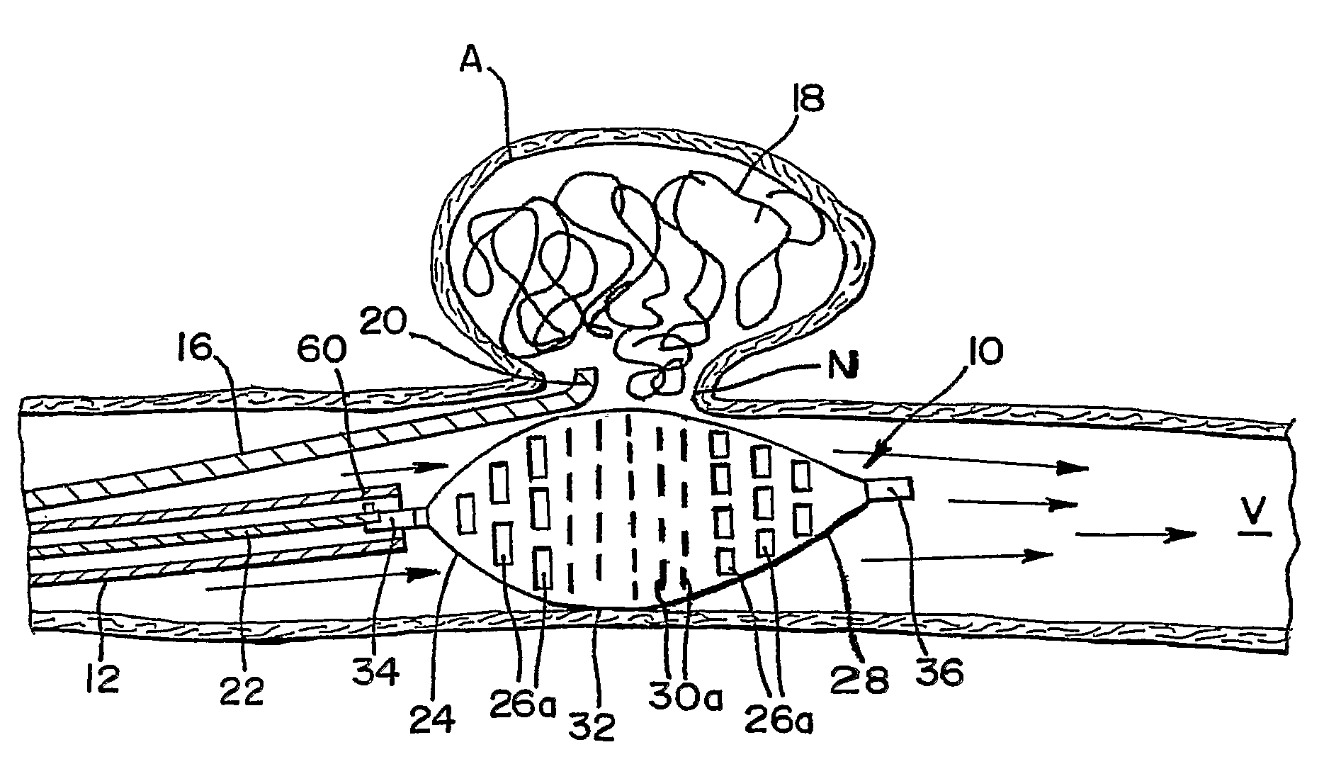
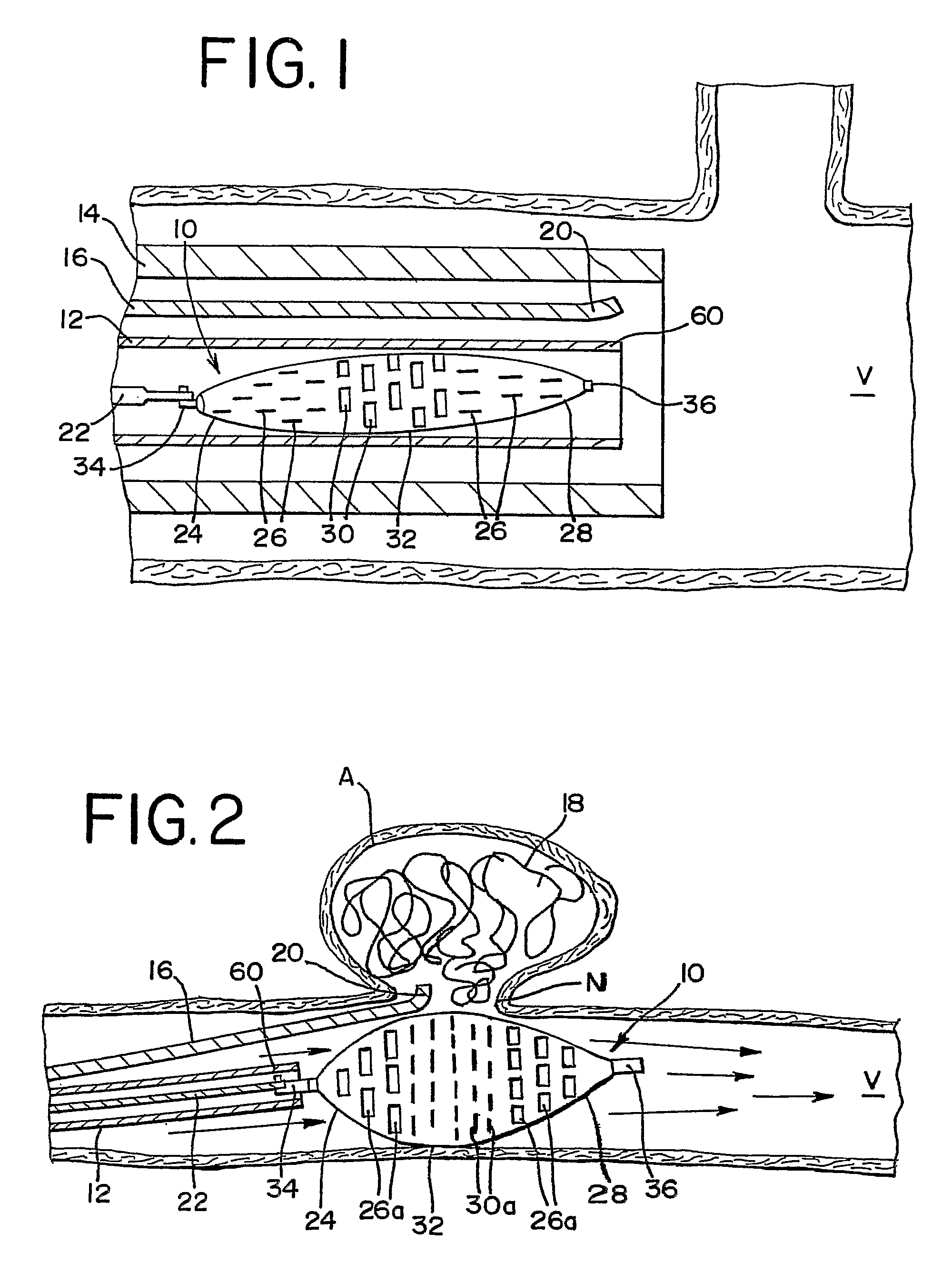
[0026]FIG. 1 illustrates an occlusion device 10 in a collapsed orientation within a delivery catheter 12. The delivery catheter 12 is carried by a gliding catheter 14, which is configured to also carry a microcatheter 16. The microcatheter 16 carries one or more embolic devices or media 18, which can be deployed to a diseased section of the vasculature, such as into an aneurysm, as seen in FIG. 2.

[0027]FIG. 2 shows occlusion device 10 in an expanded or deployed position within a body vessel V, whil...


PUM


Abstract

A method of occluding a defect in the wall of a body vessel is provided. An outlet portion of a microcatheter is delivered to the defect, then at least a body portion of a thin film occlusion device is radially expanded from a collapsed orientation to a deployed orientation for engaging the microcatheter and covering at least a portion of the defect. Thereafter, an embolic media is released into the defect from the microcatheter for facilitating thrombosis. The body portion of the occlusion device is substantially porous in the collapsed orientation, but substantially non-porous in the deployed orientation for preventing prolapse of the embolic media into the body vessel.

Description

CROSS REFERENCE TO RELATED APPLICATION[0001]This application claims priority from provisional patent application Ser. No. 60 / 619,493, filed Oct. 15, 2004, which is hereby incorporated herein by reference.FIELD OF THE INVENTION[0002]This invention generally relates to methods and medical devices for use in treating defective or diseased body vessels.DESCRIPTION OF RELATED ART[0003]An aneurysm is an abnormal bulge or ballooning of the wall of a blood vessel, which most commonly occurs in arterial blood vessels. Aneurysms typically form at a weakened point of a wall of a blood vessel. The force of the blood pressure against the weakened wall causes the wall to abnormally bulge or balloon outwardly. Aneurysms, particularly cranial aneurysms, are a serious medical condition because an aneurysm can apply undesired pressure to areas within the brain. Additionally, there is the possibility that the aneurysm may rupture or burst leading to serious medical complications including mortality.[0...

Claims


Application Information

Patent Timeline
Patent Type & Authority Patents(United States)
IPC IPC(8): A61B17/08A61F2/82
CPCA61B17/12022A61B17/12118A61B17/12172A61F2002/823A61B2017/12054
Inventor FELLER, III, FREDERICKJONES, DONALD K.SHERMAN, DARREN R.
Owner CODMAN & SHURTLEFF INC
Learn More