
Thin Film Devices for Temporary or Permanent Occlusion of a Vessel

a thin film, temporary or permanent technology, applied in the field of medical devices, can solve the problems of inaccurate occlusion, extremely small pores, time-consuming and complicated methods, etc., and achieve the effect of reducing cross-sectional extent and facilitating endoluminal deploymen

Active Publication Date: 2008-08-14
CODMAN & SHURTLEFF INC
View PDF11 Cites 2 Cited by
  • Summary
  • Abstract
  • Description
  • Claims
  • Application Information

AI Technical Summary

Benefits of technology

"The present invention provides an occlusion device with a thin film structure that can be easily deployed within the body. The thin film has a unique design with a contracted configuration during deployment and an expanded configuration within the body. The thin film has porosity that is low enough to fully or partially occlude blood flow to a vessel being treated. The porosity can provide for passage of blood flow to perforator vessels while occluding a diseased location, for body fluid filtration, and / or for tissue fixation at or adjacent to the occlusion site. The thin film mesh is made using a physical vapor deposition technique, and the thickness of the film can be controlled. The invention also provides methods for creating porous occlusion devices with a thin film structure and automatic porosity reversal upon deployment as occlusion devices."

Problems solved by technology

Accordingly, the methods described therein are time-consuming and complicated because of the need to alternate between film and sacrificial layers.
When occlusion devices are porous, especially for intercranial use, the pores are extremely small and these types of methods are not always satisfactory and can generate accuracy issues.

Method used


Image

  • Thin Film Devices for Temporary or Permanent Occlusion of a Vessel
  • Thin Film Devices for Temporary or Permanent Occlusion of a Vessel
  • Thin Film Devices for Temporary or Permanent Occlusion of a Vessel

Examples


Embodiment Construction

[0028]As required, detailed embodiments of the present invention are disclosed herein; however, it is to be understood that the disclosed embodiments are merely exemplary of the invention, which may be embodied in various forms. Therefore, specific details disclosed herein are not to be interpreted as limiting, but merely as a basis for the claims and as a representative basis for teaching one skilled in the art to variously employ the present invention in virtually any appropriate manner.

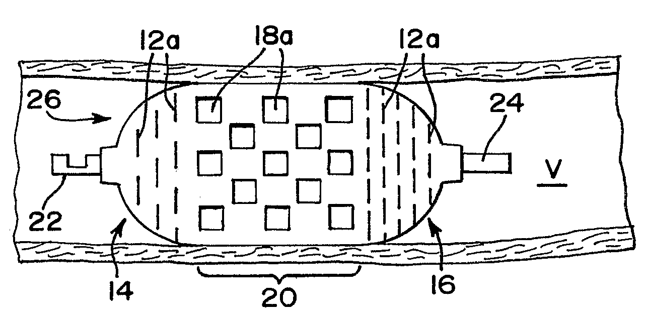
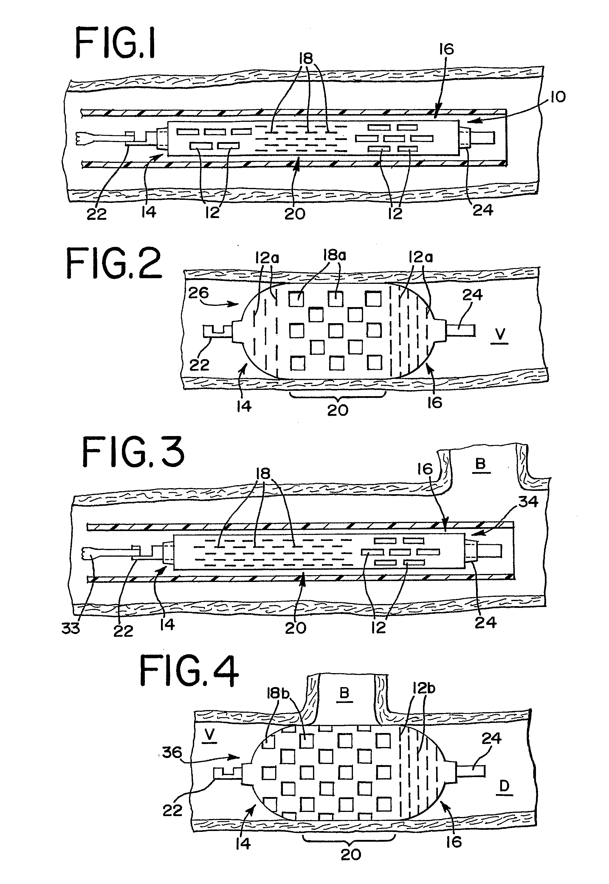
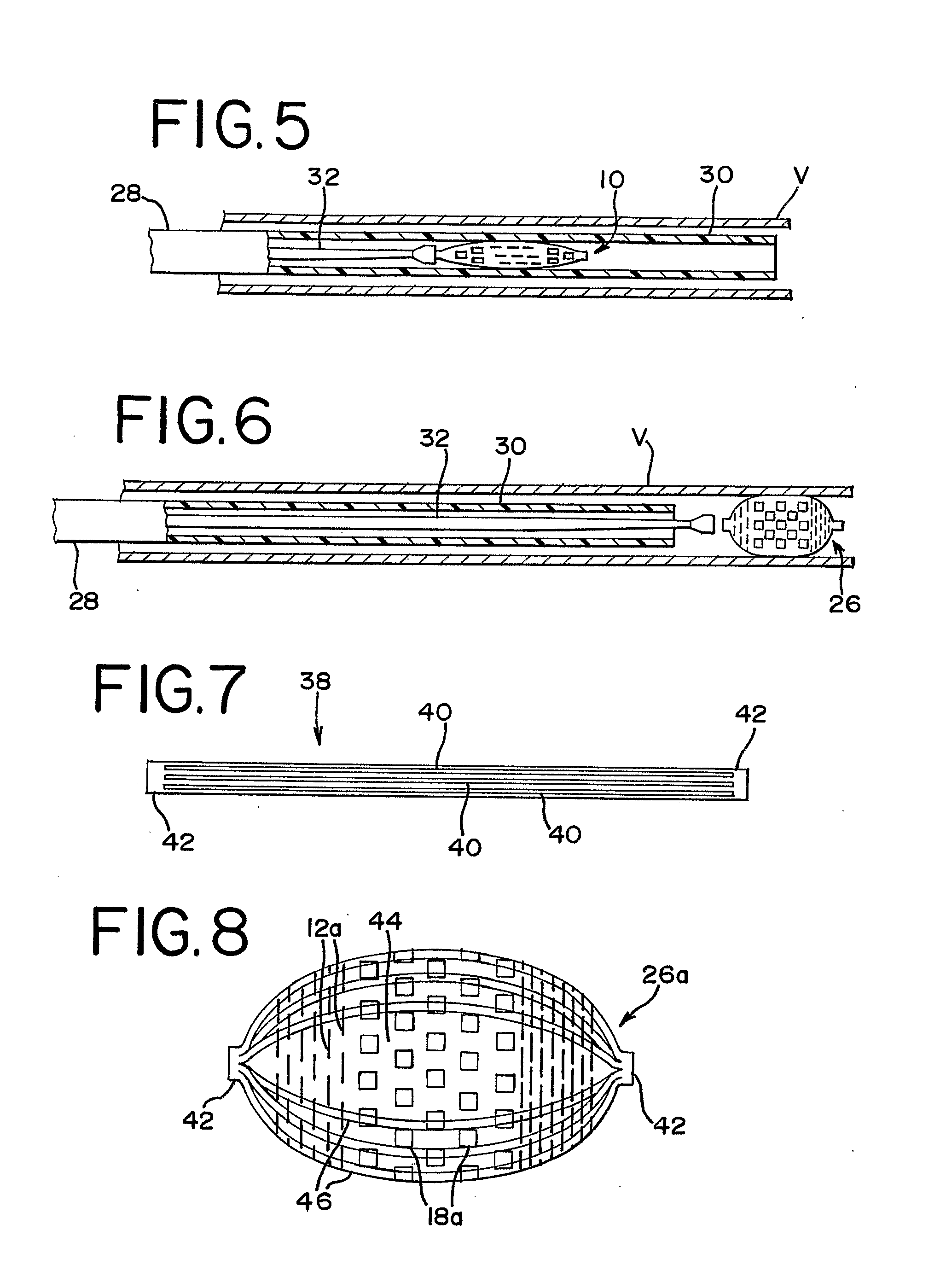
[0029]FIG. 1 illustrates an occlusion device 10 in a collapsed position. The occlusion device 10 preferably comprises a thin film mesh formed by physical vapor deposition onto a core or mandrel, as is well-known to those skilled in the art. Most preferably, a thin film of nitinol, or other material which preferably has the ability to take on a shape that had been imparted to it during manufacture, is formed. When nitinol material is used in forming the thin film, the thin film can be at the martens...


PUM


Abstract

Thin film devices implantable within a human subject for occlusion of an aneurysm or body vessel are provided. The devices are movable from an elongated, collapsed configuration for delivery to a deployed configuration within the body. Open slots in selected portions of the device telescope as the device moves to its deployed configuration, which causes the associated portions to longitudinally foreshorten and radially expand, while also decreasing in porosity for preventing blood flow. Closed slits in other portions of the device open as the device moves to its deployed configuration, which causes the associated portions to longitudinally foreshorten and radially expand, while remaining open for fluid flow or endothelialization. The occlusion devices may be either self-supporting or supported by a strut structure. Additionally, the occlusion devices may comprise a plurality of mesh layers having unaligned pore systems which further reduce porosity in desired portions of the deployed configuration.

Description

CROSS REFERENCE TO RELATED APPLICATION[0001]This application claims priority from provisional patent application Ser. No. 60 / 610,777, filed Sep. 17, 2004, which is hereby incorporated herein by reference.FIELD OF THE INVENTION[0002]This invention generally relates to medical devices that are implantable within a human subject and that have occlusion capabilities that are especially suitable for use as medical device plugs for defective or diseased body vessels. These types of devices have pores which, upon deployment, reverse configuration from open to closed or vice versa for enhanced occlusion, fixation, or other therapeutic capabilities.DESCRIPTION OF RELATED ART[0003]Medical devices that can benefit from the present invention include those that are characterized by hollow interiors and that are introduced endoluminally and expand when deployed so as to plug up a location of concern within the patient. These are devices that move between collapsed and expanded conditions or confi...

Claims


Application Information

Patent Timeline
Patent Type & Authority Applications(United States)
IPC IPC(8): A61M29/02
CPCA61B17/12022A61B17/12036A61B17/12109A61B2017/12054A61B2017/00867A61B2017/1205A61B17/12172
Inventor FELLER, FREDERICKJONES, DONALD K.SHERMAN, DARREN R.
Owner CODMAN & SHURTLEFF INC
Learn More