
Electrical actuator system for articles of furniture

a technology of electric actuators and furniture, which is applied in the direction of rigid tables, bed-tables, lighting and heating apparatus, etc., can solve problems such as continued energy consumption

Active Publication Date: 2011-01-25
LINAK AS
View PDF19 Cites 76 Cited by
  • Summary
  • Abstract
  • Description
  • Claims
  • Application Information

AI Technical Summary

Benefits of technology

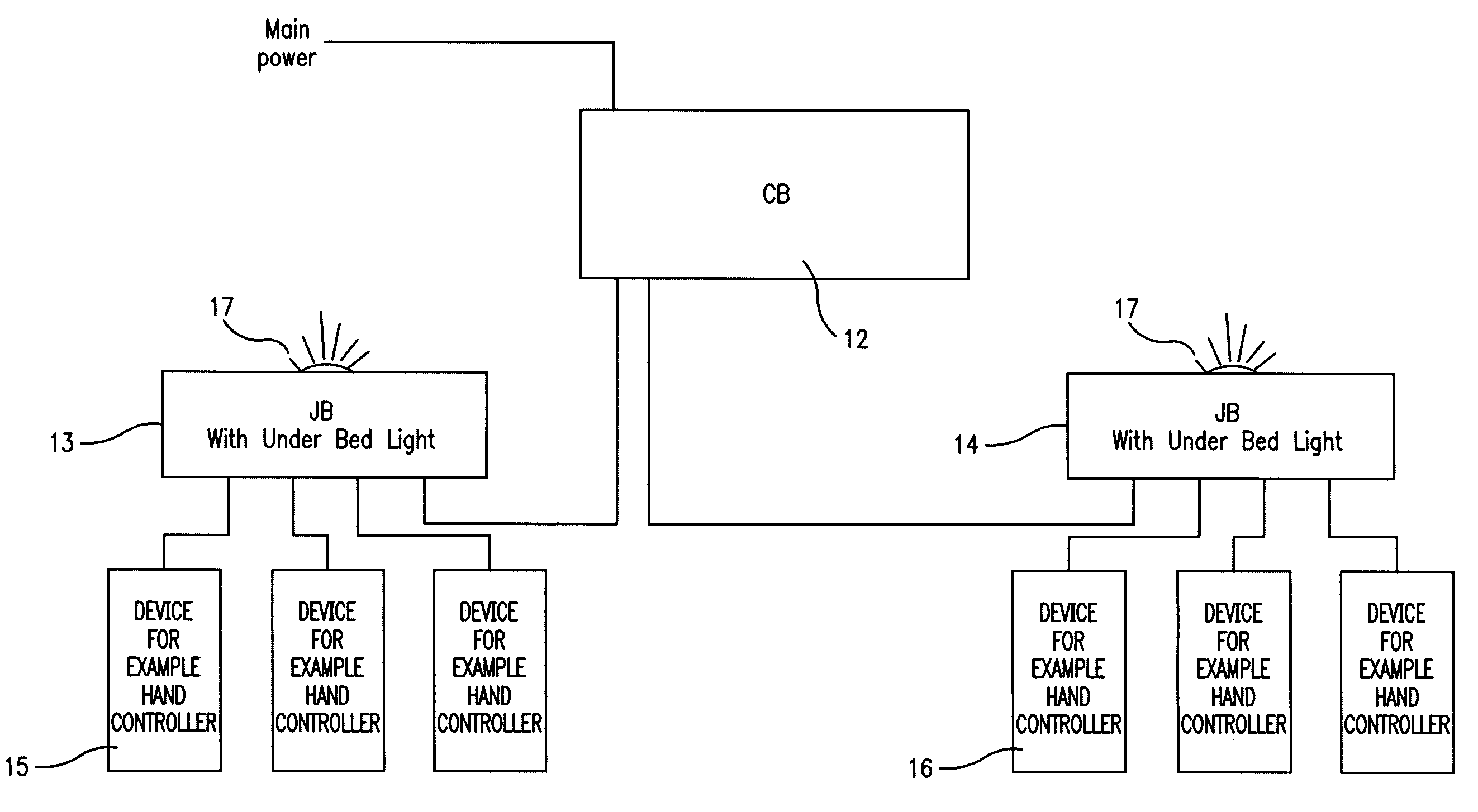
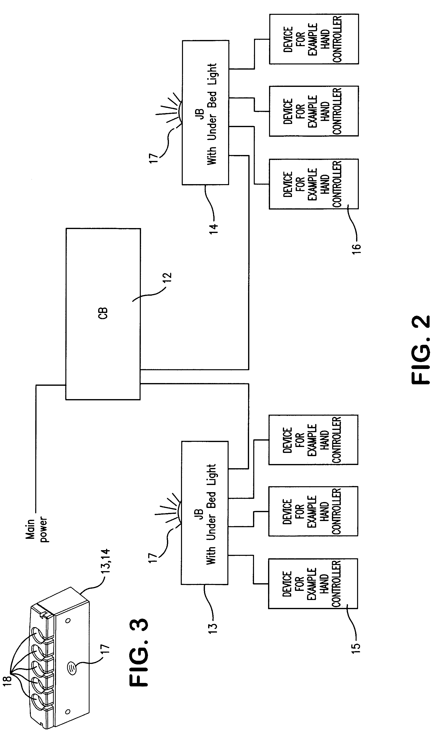
[0008]The actuator system according to the invention is characterized in that it comprises at least one junction box and that the orientation lighting is located in this with a separate control unit. This allows a more flexible location of the orientation lighting. Typically, the actuator system has just one control box comprising a mains-based power supply and a rechargeable battery package, so that the bed may be adjusted even though it is temporarily not connected to mains. Moreover, the control box comprises the control unit. All the actuators are connected to the control box. In some actuators a part of the control unit may be located in the actuators, while the rest of the control unit is located in the control box. The junction box(es) is / are cable connected to the control box. Hand controls and / or control panels and other equipment are connected to the junction boxes, but is should be understood that it does not exclude that certain hand controls, control panels or other equipment may be directly connected to the control box. As the junction box(es) is / are cable connected to the control box, said control box and thereby the orientation lighting may be placed as desired. As the orientation lighting is constructed with a separate control unit in the junction box, it is independent of the other control unit in the system. The orientation lighting can for instance be switched on all the time which of course results in a continued energy consumption, but when using light diodes as light source, this is minimal. Alternatively, it may be switched on and off via a separate switch on the junction box or via one of the controls. Another possibility is a light sensitive switch, which automatically switches on the orientation lighting when the light level in the room falls below a certain intensity.

Problems solved by technology

The orientation lighting can for instance be switched on all the time which of course results in a continued energy consumption, but when using light diodes as light source, this is minimal.

Method used


Image

  • Electrical actuator system for articles of furniture
  • Electrical actuator system for articles of furniture
  • Electrical actuator system for articles of furniture

Examples


Embodiment Construction

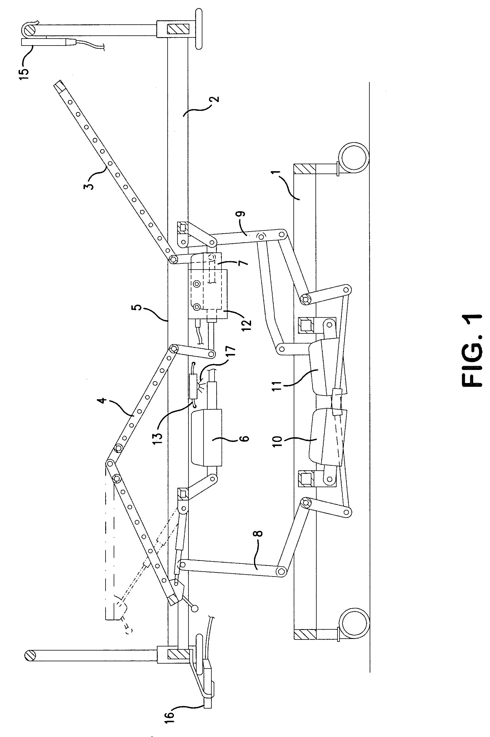
[0013]The hospital bed shown in FIG. 1 of the drawing comprises a lower frame 1 equipped with drive wheels and an upper frame 2. On the upper frame 2 is mounted an adjustable support for a mattress. The support comprises a back rest section 3, an articulated leg rest section 4 and a fixed middle section 5 between these. The back rest and leg rest section 3,4 can be adjusted by means of a respective actuator 6,7 so that the support may assume various contours. The upper frame 2 is coupled to the lower frame 1 with a link connection 8,9 at respective ends. The upper frame 2 may be raised and lowered by means of two actuators 10,11 coupled to the link connections. The actuators are connected to a control box 12 comprising a power supply for connection to mains, a rechargeable battery package and a control unit. Here, a bus system as described in WO2007 / 057014 A1 LINAK A / S is expediently used, which is hereby made part of the present application.

[0014]To the control box 12 are connected...


PUM


Abstract

An electrical actuator system, especially for hospital and care beds and patient beds, comprising a number of actuators (6,7; 10,11), a control box (12) with a mains-based power supply, and typically also a rechargeable battery package and a control unit with a microprocessor, a number of controls (15,16), an orientation light (17) for mounting under the bed. The system comprises at least one junction box (13,14) and the orientation lighting is, with its own control unit, located in this. This enables a flexible location of the lighting.

Description

BACKGROUND OF THE INVENTION[0001]1. Field of the Invention[0002]The invention relates to an electrical actuator system for articles of furniture, especially for hospital and care beds and treatment couches, and comprising a number of actuators for bringing about the adjustment of the piece of furniture, a control box connected to the actuator(s) with a mains-based power supply and typically also a rechargeable battery package and a control unit, a number of controls with a number of control buttons, and an orientation light for mounting on the piece of furniture.[0003]2. The Prior Art[0004]The orientation lighting (Under Bed Light) on hospital and care beds are used, partly by the patients to find their bearings, when getting out of the bed in darkness and partly by the staff in order to find their bearings without having to switch on the main light in the room.[0005]As an example of a bed with orientation lighting U.S. Pat. No. 6,234,642 B1 Dewert Antriebs-und Systemtechnik GmbH & ...

Claims


Application Information

Patent Timeline
IPC IPC(8): F21V33/00
CPCA61G7/018A61G7/015A61G7/012
Inventor JENSEN, SVEND ERIK KNUDSEN
Owner LINAK AS
Learn More