Motor having chucking device and disk driving apparatus including same

a technology of chucking device and drive device, which is applied in the direction of magnetic recording, data recording, instruments, etc., can solve the problems of disc deflecting during its rotation, vibration may be generated, error may possibly be generated, etc., and achieve high-precision positioning of the disk support surface, preventing deformation of the fixing portion, and improving the coaxiality between the center axis and the center of the rotor magnet.

Active Publication Date: 2011-01-18
NIDEC CORP
View PDF15 Cites 0 Cited by
  • Summary
  • Abstract
  • Description
  • Claims
  • Application Information

AI Technical Summary

Benefits of technology

[0007]The present invention provides a motor with a highly accurate chucking device by which a turntable part of the chucking device is prevented from deformation even if a disk support surface of the chucking device is pressed when mounting the motor within a disk driving apparatus, and also provides a disk driving apparatus equipped with the motor.
[0011]With such configuration, it is possible to highly accurately position the disk support surface with no influence of deflection of the upper surface of the rotor holder by keeping the outer table having the disk support surface spaced apart from the upper surface of the rotor holder. Subsequently, by fixing the rotor holder to the shaft, coaxiality between the center axis and the center of the rotor magnet can be improved. Since the inner table is made of a metal and fixed to the shaft, it is possible to prevent deformation of the fixing portion of the inner table and the shaft, even when an axially acting force is applied to the disk support surface. Also, since the moment generated in the inner table and the outer table becomes smaller than the moment which would be generated when the outer table is fixed to the shaft, it is possible to prevent deformation of the fixing portion of the outer table and the inner table. Therefore, it is possible to reduce rotational deflection of the disk support surface.
[0016]With such configuration, it is possible to highly accurately position the disk support surface with no influence of deflection of the upper surface of the rotor holder by keeping the outer table having the disk support surface spaced apart from the upper surface of the rotor holder. Subsequently, by fixing the rotor holder to the shaft, coaxiality between the center axis and the center of the rotor magnet can be improved. Since the inner table is made of a metal and fixed to the shaft, it is possible to prevent deformation of the fixing portion of the inner table and the shaft, even when an axially acting force is applied to the disk support surface. Also, since the moment generated in the inner table and the outer table becomes smaller than the moment which would be generated when the outer table is fixed to the shaft, it is possible to prevent deformation of the fixing portion of the outer table and the inner table. Therefore, it is possible to reduce rotational deflection of the disk support surface.
[0020]With such configuration, it is possible to highly accurately position the disk support surface with no influence of deflection of the upper surface of the rotor holder by keeping the outer table having the disk support surface spaced apart from the upper surface of the rotor holder. Subsequently, by fixing the rotor holder to the shaft, coaxiality between the center axis and the center of the rotor magnet can be improved. Since the inner table is made of a metal and fixed to the shaft, it is possible to prevent deformation of the fixing portion of the inner table and the shaft, even when an axially acting force is applied to the disk support surface. Owing to the fact that the moment generated in the inner table and the outer table becomes smaller than the moment which would be generated when the outer table is fixed to the shaft, it is possible to prevent deformation of the fixing portion of the outer table and the inner table. Therefore, it is possible to reduce rotational deflection of the disk support surface.
[0021]In accordance with the aspects of the present invention, it is possible to provide a motor with a highly accurate chucking device by which a turntable part of the chucking device is prevented from deformation even if a disk support surface of the chucking device is pressed when mounting the motor within a disk driving apparatus, and also to provide a disk driving apparatus equipped with the motor.

Problems solved by technology

During the course of fitting a motor to a disk driving apparatus, however, there is a possibility that a worker who engages in the task of assembling the disk driving apparatus may inadvertently press a disk support surface of a chucking device.
As a result, a disk may be deflected during its rotation and an error may possibly be generated when recording information on or reproducing information from the disk.
Another problem resides in that vibration may be generated due to deflection of the disk during its rotation.

Method used


Image

  • Motor having chucking device and disk driving apparatus including same
  • Motor having chucking device and disk driving apparatus including same
  • Motor having chucking device and disk driving apparatus including same

Examples


Embodiment Construction

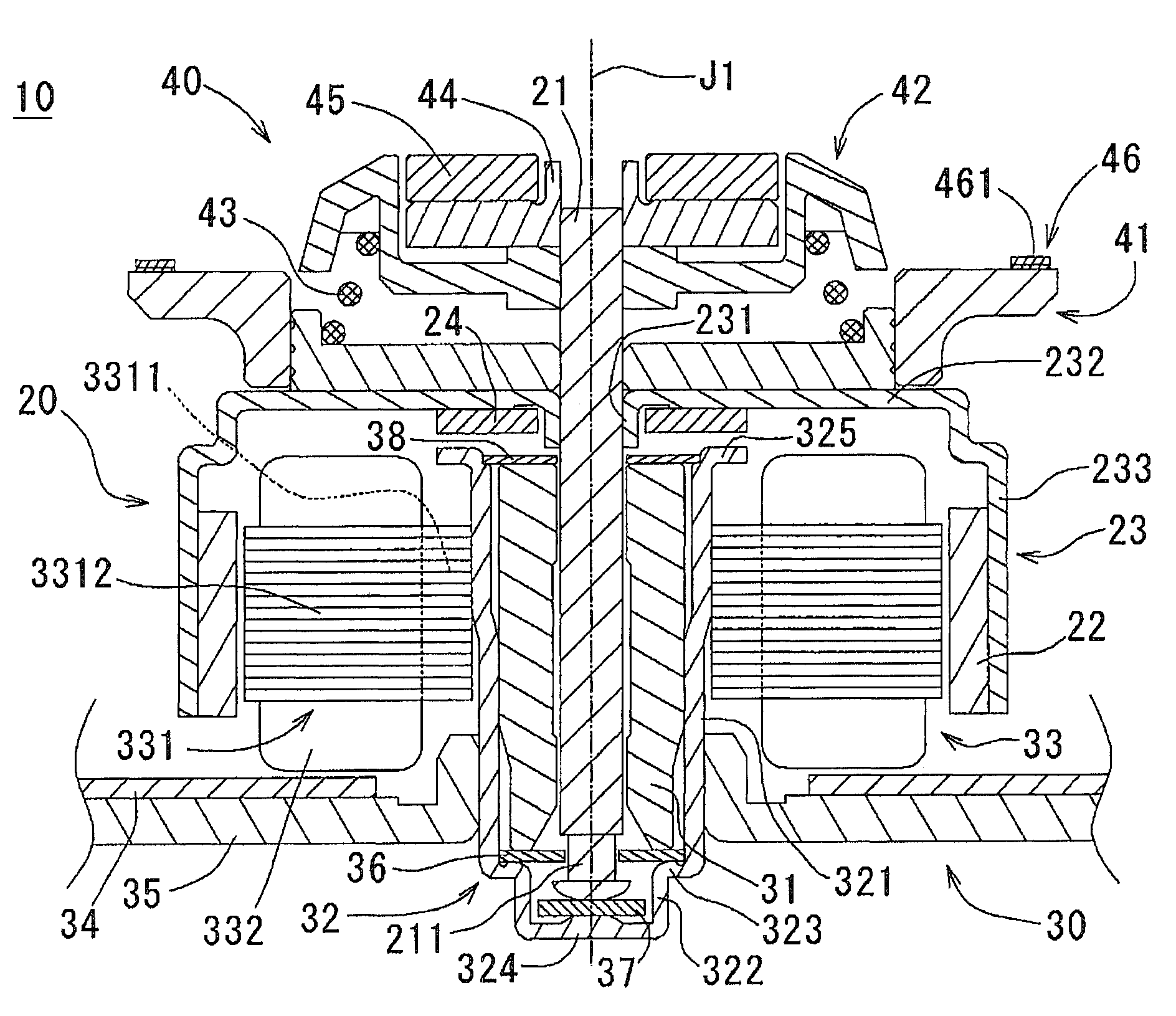
[0034]Referring to FIGS. 1 through 12, preferred embodiments of the present invention will be described in detail. It should be noted that in the explanation of the present invention, when positional relationships among and orientations of the different components are described as being up / down or left / right, ultimately positional relationships and orientations that are in the drawings are indicated; positional relationships among and orientations of the components once having been assembled into an actual device are not indicated. Meanwhile, in the following description, an axial direction indicates a direction parallel to a rotation axis, and a radial direction indicates a direction perpendicular to the rotation axis.

[0035]

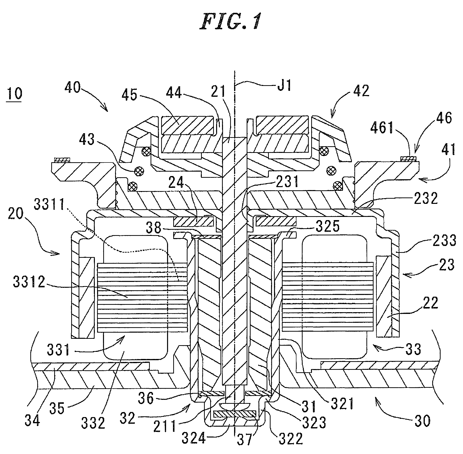
[0036]One embodiment of a motor in accordance with the present invention will now be described with reference to FIG. 1, which is an axially-cut schematic section view of the motor.

[0037]Referring to FIG. 1, a motor 10 of the present invention includes a rotatin...


PUM

PropertyMeasurementUnit
resilientaaaaaaaaaa
adhesiveaaaaaaaaaa
distanceaaaaaaaaaa

Abstract

A motor includes a chucking device to hold a disk having a central opening in a detachable manner. In the chucking device, a turntable part is arranged above a rotor holder and has a disk support surface for supporting the disk. An axially slidable cone part is arranged above the turntable part. A resilient member is axially arranged between the turntable part and the cone part upwardly biases the cone part. Further, the turntable part includes an inner table made of a metal and fixed to the shaft, and an outer table made of a resin material and fixed to an outside of the inner table. The outer table has the disk support surface and is axially spaced apart from the rotor holder in a position where the inner table and the outer table are fixed to each other.

Description

FIELD OF THE INVENTION[0001]The present invention relates to a motor provided with a chucking device and, more particularly, to a motor capable of preventing deflection of a turntable of a chucking device even when a force is imparted on the turntable. The present invention also pertains to a disk driving apparatus equipped with the motor.BACKGROUND OF THE INVENTION[0002]Conventionally, a motor for rotating a disk is provided at its top portion with a chucking device that removably holds the disk. The chucking device includes a centering case which brings the center of the disk into alignment with the rotational axis of the motor (hereinafter simply referred to as “centering”) and a turntable having a disk support surface for supporting the disk. In general, the chucking device is fastened to a rotating shaft of the motor (see, e.g., Japanese Patent Laid-open Publication No. H5-334779 that discloses a conventional motor provided with a chucking device).[0003]A structure of the conve...

Claims


Application Information

Patent Timeline
Patent Type & Authority Patents(United States)
IPC IPC(8): G11B17/04
CPCG11B17/0282G11B17/02G11B17/028
Inventor ITO, HARUHIKOYAMANE, TAKUYAKAWAMURA, SHIGEOKITAMURA, YOSHIHISA
Owner NIDEC CORP
Why Eureka
Try Eureka