
Miniature antenna for a motor vehicle

a technology for motor vehicles and antennas, applied in the direction of antenna adaptation in movable bodies, radiating elements structural forms, electrical devices, etc., can solve the problems of limited telecommunication services included in automobiles, and achieve the effect of less opportunity to steal the antenna, and enhancing the aesthetics of the vehicl

Active Publication Date: 2011-01-11
ADVANCED AUTOMOTIVE ANTENNAS
View PDF12 Cites 26 Cited by
  • Summary
  • Abstract
  • Description
  • Claims
  • Application Information

AI Technical Summary

Benefits of technology

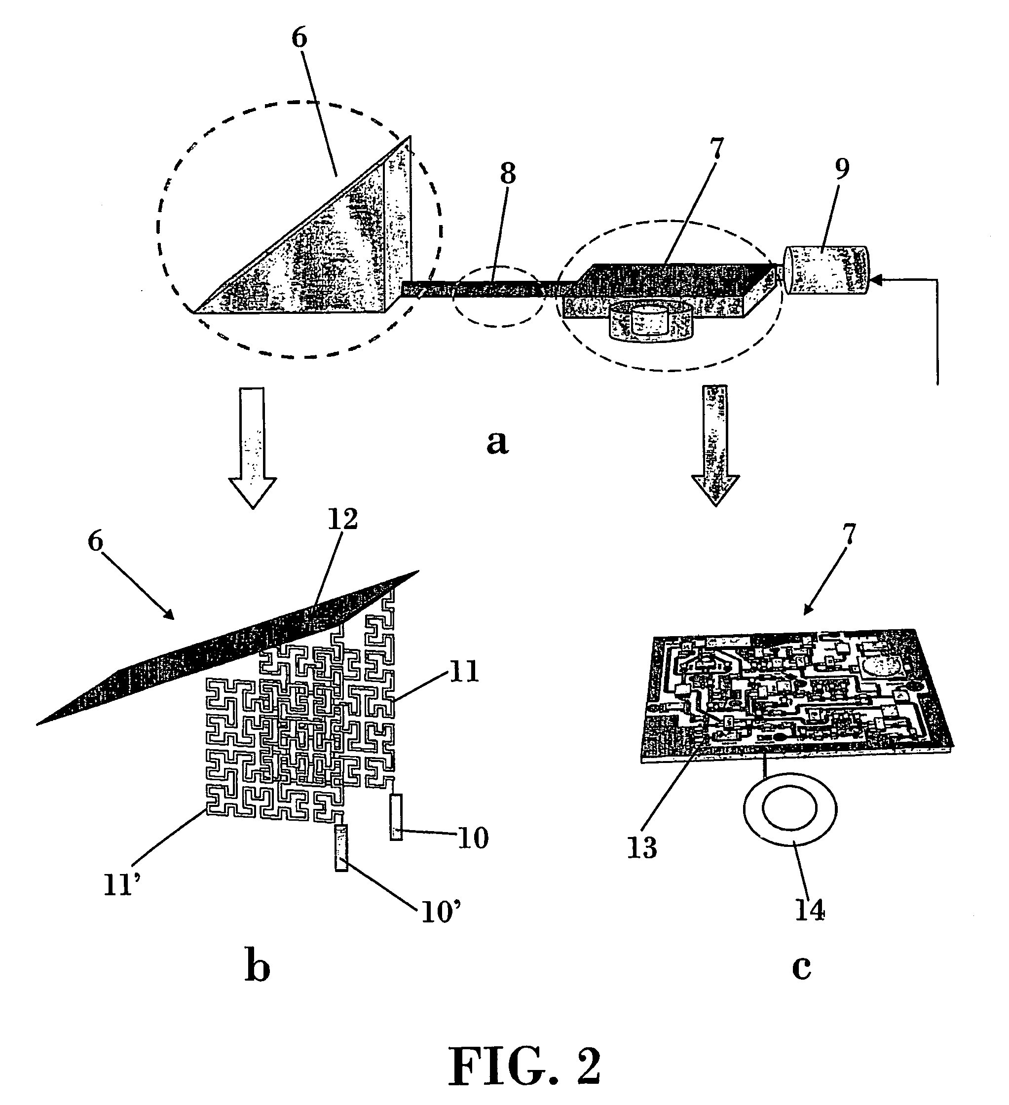
[0008]Placing the antenna in an internal mirror of the motor vehicle, such as a rear-view mirror, may enhance the aesthetics of the vehicle, provide less opportunity to steal the antenna, and provide other advantages. Attaching the antenna to the roof of the motor vehicle may also provide advantages, such as enhancing the aesthetics of the vehicle, avoiding damage suffered by a conventional car antenna, providing a compact antenna solution with less possibility of being stolen, and other advantages.
[0009]Some example features of the antenna described herein may include:
[0010]Implementation in a robust electrical substrate or dielectric support to help ensure the correct position and viability of the different metallic parts of the antenna.
[0011]Placement in a remote position with a specific connection to the vehicle's ground or to the physical support for the antenna with connections to the vehicle's ground.
[0012]A plastic antenna housing to help ensure waterproof protection of the antenna board and active system components, fixation and position of the antenna in the car.
[0013]The capacity to integrate another antennas services into the same space.
[0014]A further aspect of the invention refers to a motor vehicle or to a vehicle's component, having at least one antenna system as the one previously described.

Problems solved by technology

Until recently, the telecommunication services included in an automobile were limited to a few systems, mainly the analogical radio reception (AM / FM bands).

Method used


Image

  • Miniature antenna for a motor vehicle
  • Miniature antenna for a motor vehicle
  • Miniature antenna for a motor vehicle

Examples


Embodiment Construction

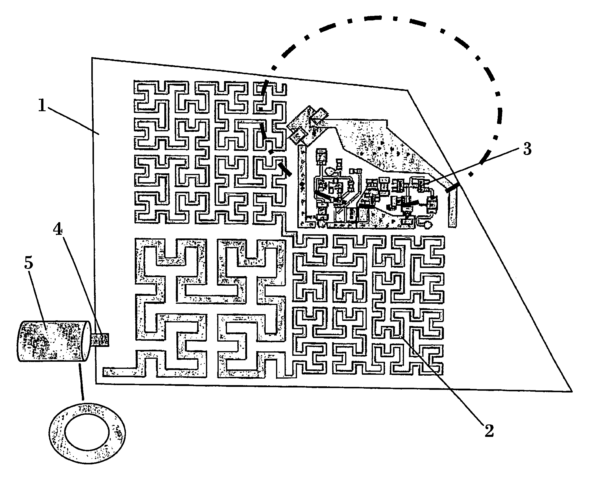
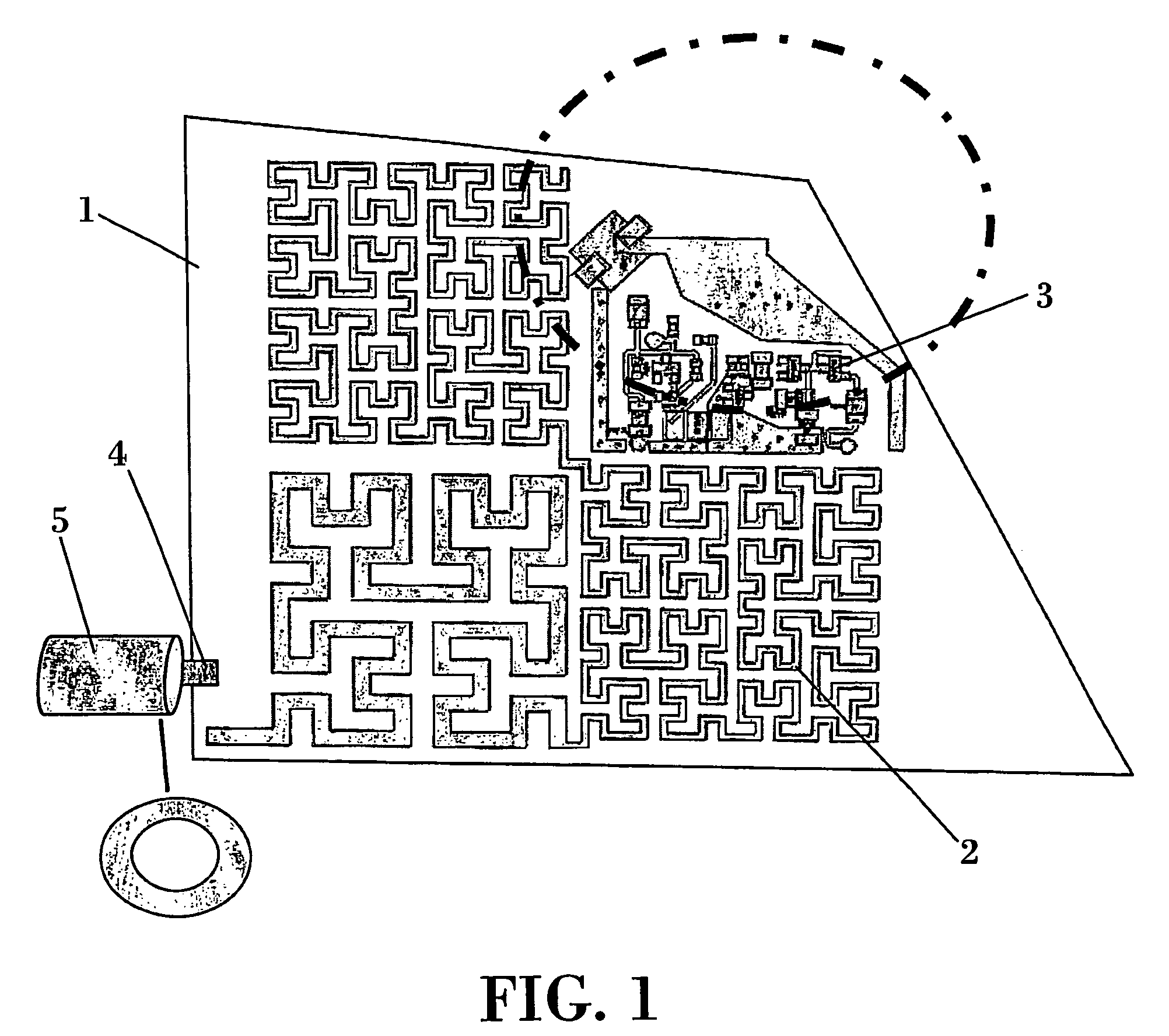
[0034]FIG. 1 shows an antenna system according to one embodiment of the present invention, which includes an electric substrate (1), an antenna curve (2), an AM / FM active module (3), a ground point connection (4), and a coaxial output (5). The electrical substrate (1) of FIG. 1 may be a robust electrical substrate or dielectric support that helps to ensure the correct position and viability of the different metallic parts of the antenna. The antenna curve (2) of FIG. 1 is a conductive trace that includes a space-filling, grid-dimension curve and / or has a desired box counting dimension, as described below. The geometry of the antenna curve may, for example, include a Hilbert curve based design, as it is the case of FIG. 1.

[0035]The whole antenna curve or at least a portion of it may preferably have a box-counting dimension or grid dimension larger than 1.5. In general, the higher the box-counting or grid dimension, the higher the antenna size compression. In some cases, it has been f...


PUM


Abstract

The present invention relates to a miniature antenna for a motor vehicle. The antenna may, for example, be a printed board miniature radio antenna for AM / FM signal reception. The antenna may, for example, be placed in an internal mirror of a motor vehicle or on an exterior surface of the motor vehicle, such as the vehicle's roof. The antenna is shaped as a curve of conductive material in which the geometry of at least a part of said curve comprises a space-filling curve or a grid dimension curve.

Description

OBJECT OF THE INVENTION[0001]The technology described in this patent document relates generally to a miniature antenna for a motor vehicle. The antenna may, for example, be a printed board miniature radio antenna for AM / FM signal reception. The antenna may, for example, be placed in an internal mirror of a motor vehicle or on an exterior surface of the motor vehicle, such as the vehicle's roof. In some examples, the antenna may be grouped with other antennas for wireless applications or may be included in a group of antennas to improve the signal reception.[0002]It is one object of the present invention to provide miniature antennas that can be fitted inside a component of the vehicle or that can be mounted on the external surface of a vehicle.BACKGROUND OF THE INVENTION[0003]Until recently, the telecommunication services included in an automobile were limited to a few systems, mainly the analogical radio reception (AM / FM bands). The most common solution for these systems is the typ...

Claims


Application Information

Patent Timeline
Patent Type & Authority Patents(United States)
IPC IPC(8): H01Q1/32
CPCH01Q1/1271H01Q1/3266H01Q1/3275H01Q1/36H01Q1/38
Inventor ORTIGOSA, ENRIQUE MARTINEZBALIARDA, CARLES PUENTE
Owner ADVANCED AUTOMOTIVE ANTENNAS
Learn More