
Package on-package secure module having BGA mesh cap

a technology of a security mesh and a package, which is applied in the direction of semiconductor devices, semiconductor/solid-state device details, electrical apparatus, etc., can solve the problems of insufficient security mesh, insufficient security mesh, and inability to secure electronic components, etc., to achieve high production efficiency, low cost, and high volume

Inactive Publication Date: 2011-01-11
MAXIM INTEGRATED PROD INC
View PDF20 Cites 73 Cited by
  • Summary
  • Abstract
  • Description
  • Claims
  • Application Information

AI Technical Summary

Benefits of technology

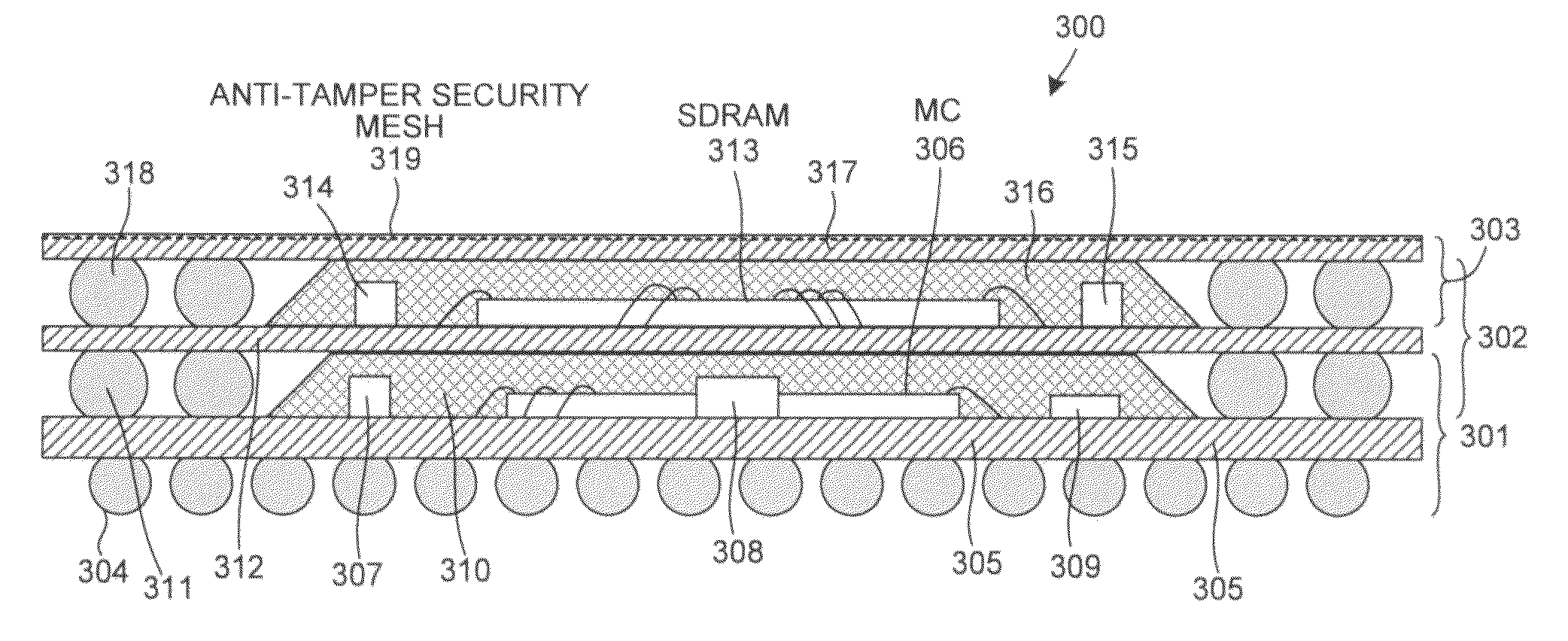
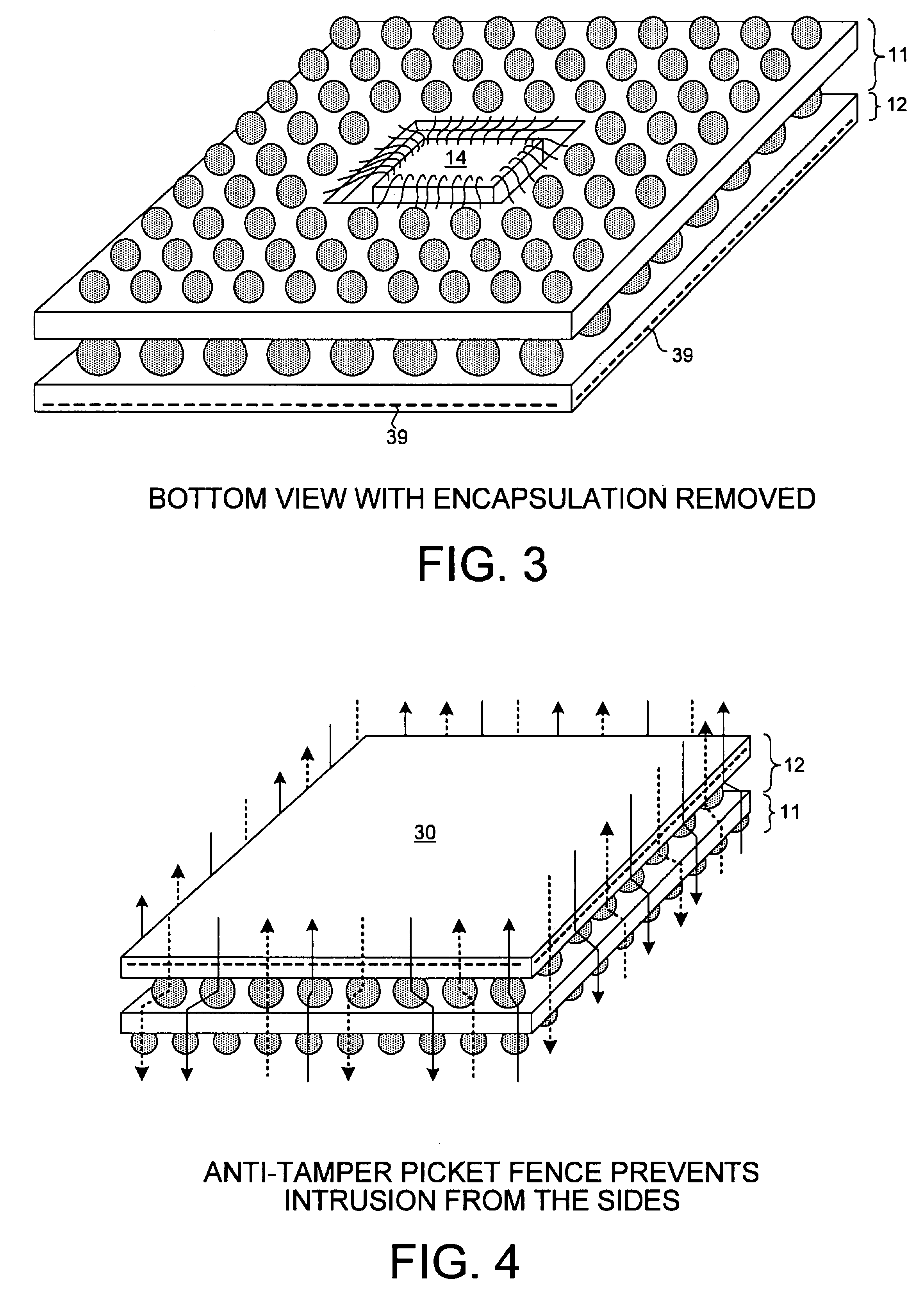
The patent describes a secure module that is used in a point of sale terminal. The module includes a first and second BGA package portions that are securely connected together. The first BGA package portion includes a substrate member and a first integrated circuit die, while the second BGA package portion includes a substrate member and a second integrated circuit die. The first and second BGA package portions are embedded in a first and second anti-tamper security mesh, which protects against intrusion from above, sides, and below. The module also includes a specialized integrated circuit that detects tampering and is designed for use in a point of sale terminal. The specialized integrated circuit and memory integrated circuit can be different versions of the module without changing the design of the specialized integrated circuit or the substrate member. The package-on-package secure module includes a first and second BGA package portions that are piggy-back mounted and a BGA mesh cap that protects against intrusion from above. The technical effects of this patent include improved security against tampering and a more compact and efficient design for the secure module.

Problems solved by technology

If a thief were to attempt to probe through the mesh to get access to the integrated circuit, then certain of the conductors would likely be cut or pushed together.
Unfortunately, providing a security mesh for a point or sale terminal circuit is typically undesirably expensive and / or is inadequate.

Method used


Image

  • Package on-package secure module having BGA mesh cap
  • Package on-package secure module having BGA mesh cap
  • Package on-package secure module having BGA mesh cap

Examples


Embodiment Construction

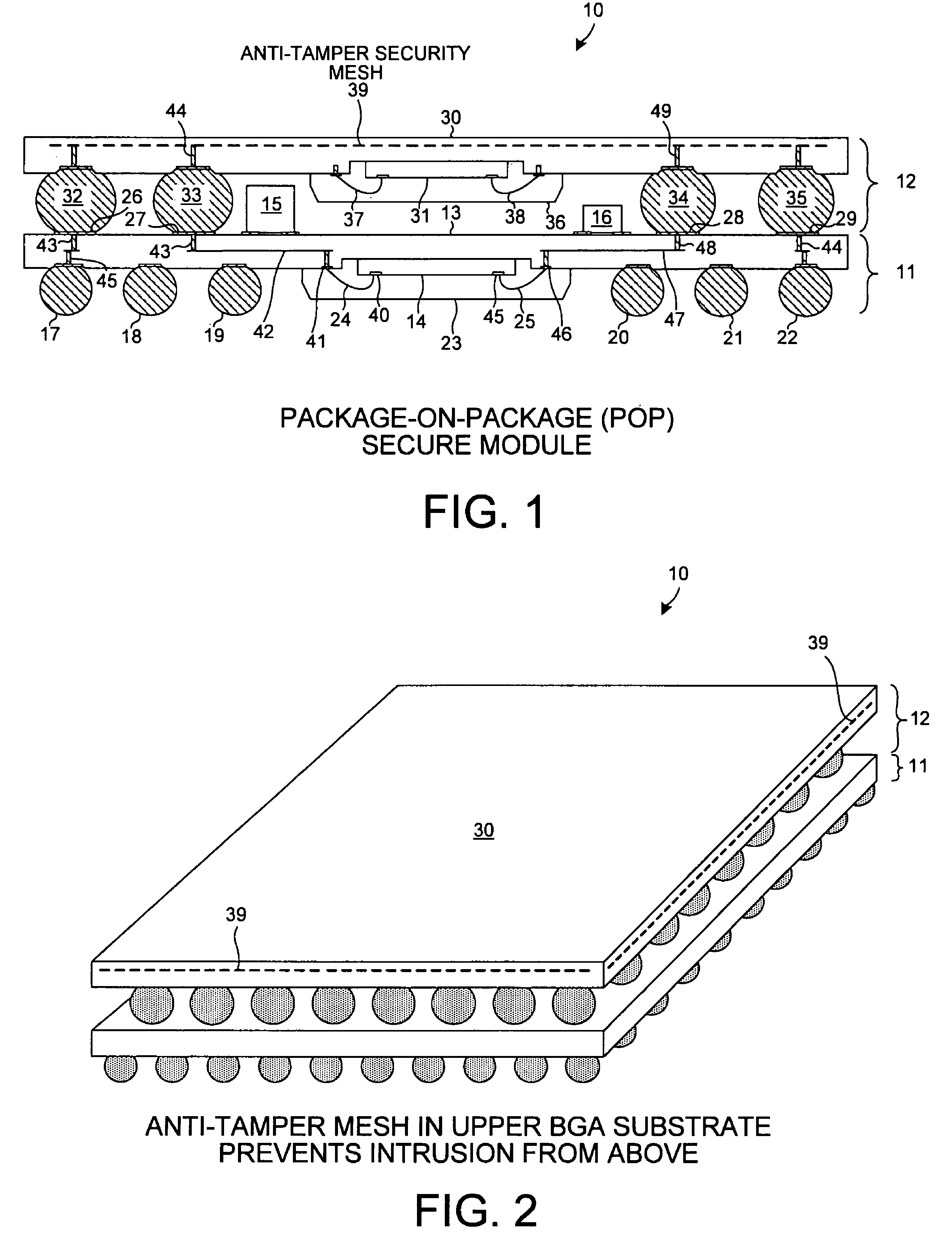
[0044]FIG. 1 is a simplified cross-sectional diagram of a novel Package-On-Package (POP) secure module 10. POP secure module 10 includes a first Ball Grid Array (BGA) package portion 11, and a second BGA package portion 12. First BGA package portion 11 includes a substrate member 13, an integrated circuit die 14, an array of bond balls, an array of lands, and discrete components 15 and 16. Six of the bond balls 17-22 are illustrated in the cross-sectional view. Integrated circuit die 14 is connected by wire bonds to substrate member 13 and is encapsulated with a block of encapsulant 23 such as epoxy potting encapsulant. Two of the bond wires 24 and 25, and four of the lands 26-29 are illustrated in the cross-sectional view.

[0045]Second BGA package portion 12 includes a substrate member 30, an integrated circuit die 31, and an array of bond balls. Four of the bond balls 32-35 are illustrated in the cross-sectional view. Integrated circuit die 31 is connected by wire bonds to substrat...


PUM


Abstract

A package-on-package (POP) secure module includes a BGA mesh cap, a first BGA package, and a second BGA package. The first BGA package includes a first integrated circuit (for example, a microcontroller that includes tamper detect logic). The second BGA package includes a second integrated circuit (for example, a memory). The second BGA package is piggy-back mounted to the first BGA package and the BGA mesh cap is piggy-back mounted to the second BGA package. A printed circuit board substrate member of the BGA mesh cap includes an embedded anti-tamper mesh. This mesh is connected in a protected manner within the module to the first integrated circuit. When the module is in use, a mesh embedded in an underlying printed circuit board is coupled to the BGA cap mesh so that both anti-tamper meshes are controlled by the tamper detect logic.

Description

CROSS REFERENCE TO RELATED APPLICATION[0001]This application is a continuation-in-part of, and claims priority under 35 U.S.C. §120 from, nonprovisional U.S. patent application Ser. No. 11 / 786,871, entitled “Package-On-Package Secure Module Having Anti-Tamper Mesh In The Substrate Of The Upper Package,” by Steven M. Pope and Ruben C. Zeta, filed on Apr. 13, 2007, the subject matter of which is incorporated herein by reference.TECHNICAL FIELD[0002]The described embodiments relate to securing electronic components and data from unauthorized access, and more particularly to securing electronic components in Point Of Sale (POS) terminals.BACKGROUND INFORMATION[0003]Purchases are often made using an electronic device called a Point Of Sale (POS) terminal. The POS terminal is typically coupled to a financial institution via an electronic communication link. A customer in a store may, for example, present a debit card, credit card, cash card or smart card to the store's cashier for payment...

Claims


Application Information

Patent Timeline
Patent Type & Authority Patents(United States)
IPC IPC(8): H01L21/44H01L21/56H01L23/488
CPCH01L25/0655H01L25/0657H01L25/105H01L23/576H01L25/16H01L23/3128H01L2924/10253H01L23/647H01L24/48H01L25/18H01L2224/16225H01L2224/32145H01L2224/48091H01L2224/48235H01L2225/0651H01L2225/06517H01L2225/06527H01L2225/06572H01L2225/06575H01L2924/14H01L2924/15153H01L2924/15165H01L2924/15174H01L2924/15311H01L2924/1532H01L2924/15331H01L2924/19041H01L2924/3025H01L2225/1058H01L2924/19105H01L2924/15321H01L2924/15192H01L2224/73265H01L2224/32225H01L2225/06568H01L2225/06558H01L2924/01019H01L2224/16227H01L2924/00014H01L2224/48227H01L2924/00012H01L2924/00H01L24/73H01L2924/181H01L2224/45099H01L2224/45015H01L2924/207H01L23/12H01L23/48
Inventor EATON, DAVID D.STAAB, DAVID R.ZETA, RUBEN C.
Owner MAXIM INTEGRATED PROD INC
Learn More