
Stethoscope cleaning assembly

a technology of cleaning assembly and stethoscope, which is applied in the field of stethoscope cleaning assembly, can solve the problems of requiring the availability of wipes, and generally not being integrated into routine physician practice, so as to facilitate replacement and/or maintenance, avoid this potentially serious contamination risk, and avoid the effect of contamination

Active Publication Date: 2011-01-11
SEEDLINGS LIFE SCI VENTURES
View PDF33 Cites 8 Cited by
  • Summary
  • Abstract
  • Description
  • Claims
  • Application Information

AI Technical Summary

Benefits of technology

"The present invention is a cleaning assembly for a stethoscope that is designed to effectively clean the head portion of the stethoscope. The cleaning assembly includes a housing with an interior space that contains a cleaning fluid and various components for cleaning the stethoscope. The cleaning assembly is structured to allow the stethoscope head to pass through the housing and be exposed to the cleaning fluid during a cleaning procedure. The cleaning fluid is applied to the exposed surfaces of the stethoscope head using a swiping action, which eliminates the need for a reciprocal movement of the head. The cleaning assembly is designed to be efficient, safe, and effective without the need for supplemental power."

Problems solved by technology

However, because of time demands, emergency situations and other situations which frequently occur, a health care provider may only perform a minimal cleaning of the instrument on an occasional basis.
Although, these cursory cleaning procedures may be effective, they are burdensome, time consuming and require the ready availability of these wipes.
Furthermore, while available and inexpensive, these wipes have generally not been integrated into routine physician practice.
However, many known or conventional devices, while being at least minimally operative to accomplish their intended purpose, also suffer from numerous disadvantages.
Such disadvantages generally relate to accomplishing an effective cleaning, disinfecting or possible sterilization of the instrument and the fact that many of such known cleaning devices are difficult or too time consuming for convenient use.
The transfer of pathogenic bacteria from one patient to another is a major cause of healthcare associated infections.
However, the majority of healthcare workers do not clean or disinfect their stethoscope after each patient encounter.
Common reasons for not cleaning or disinfecting stethoscopes are that the alcohol pads and swabs are not readily available, are messy, time consuming to use and require disposal.
However, the Centers for Disease Control and Prevention also recommends that for all patients receiving care in a hospital, an item of patient care equipment must not be reused on another patient until it has been cleaned and reprocessed appropriately.
Further, any such cleaning device that is located in a patient's room or in an examination area may, over time, have its exterior surface contaminated by pathogenic bacteria.

Method used


Image

  • Stethoscope cleaning assembly
  • Stethoscope cleaning assembly
  • Stethoscope cleaning assembly

Examples


Embodiment Construction

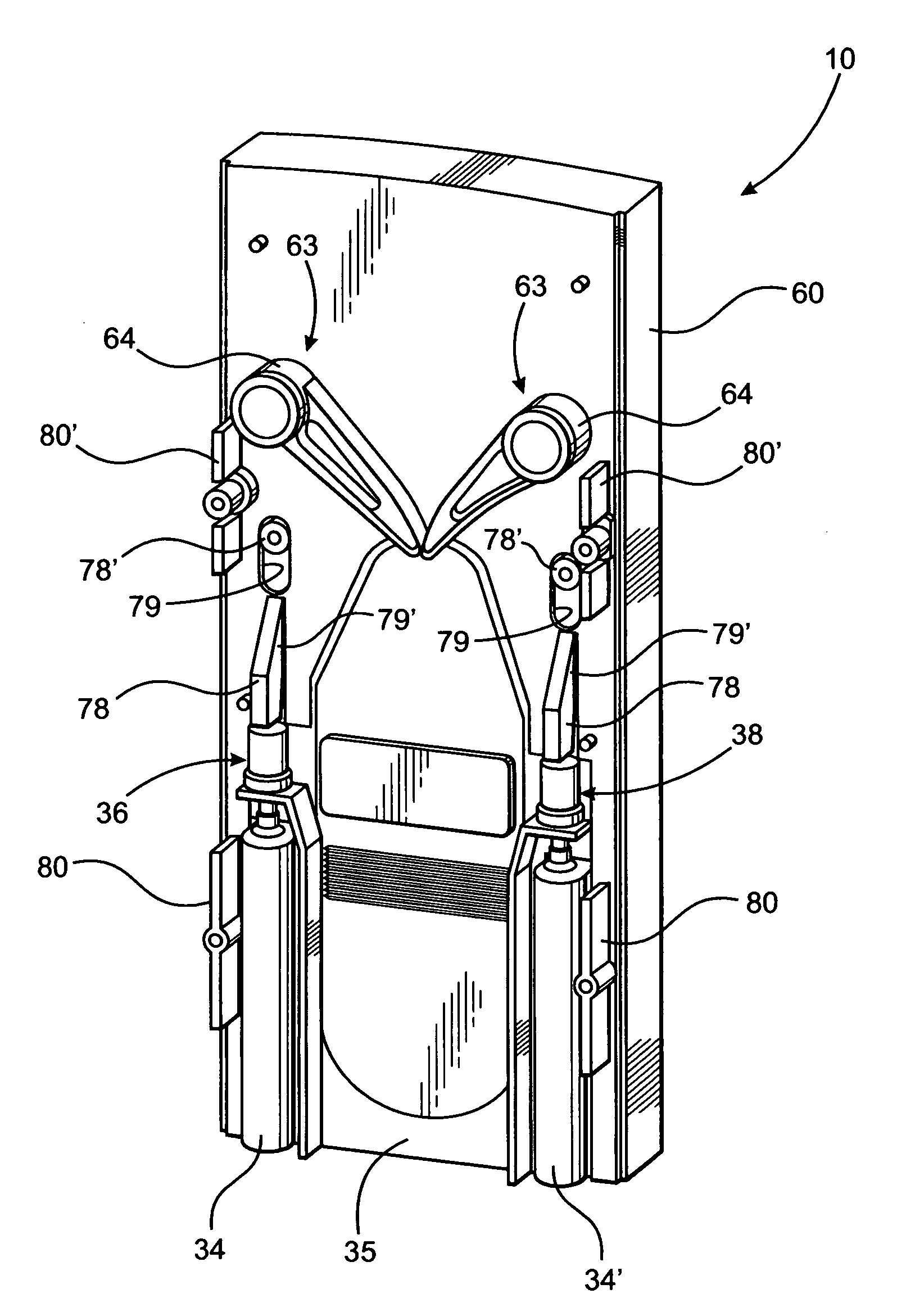
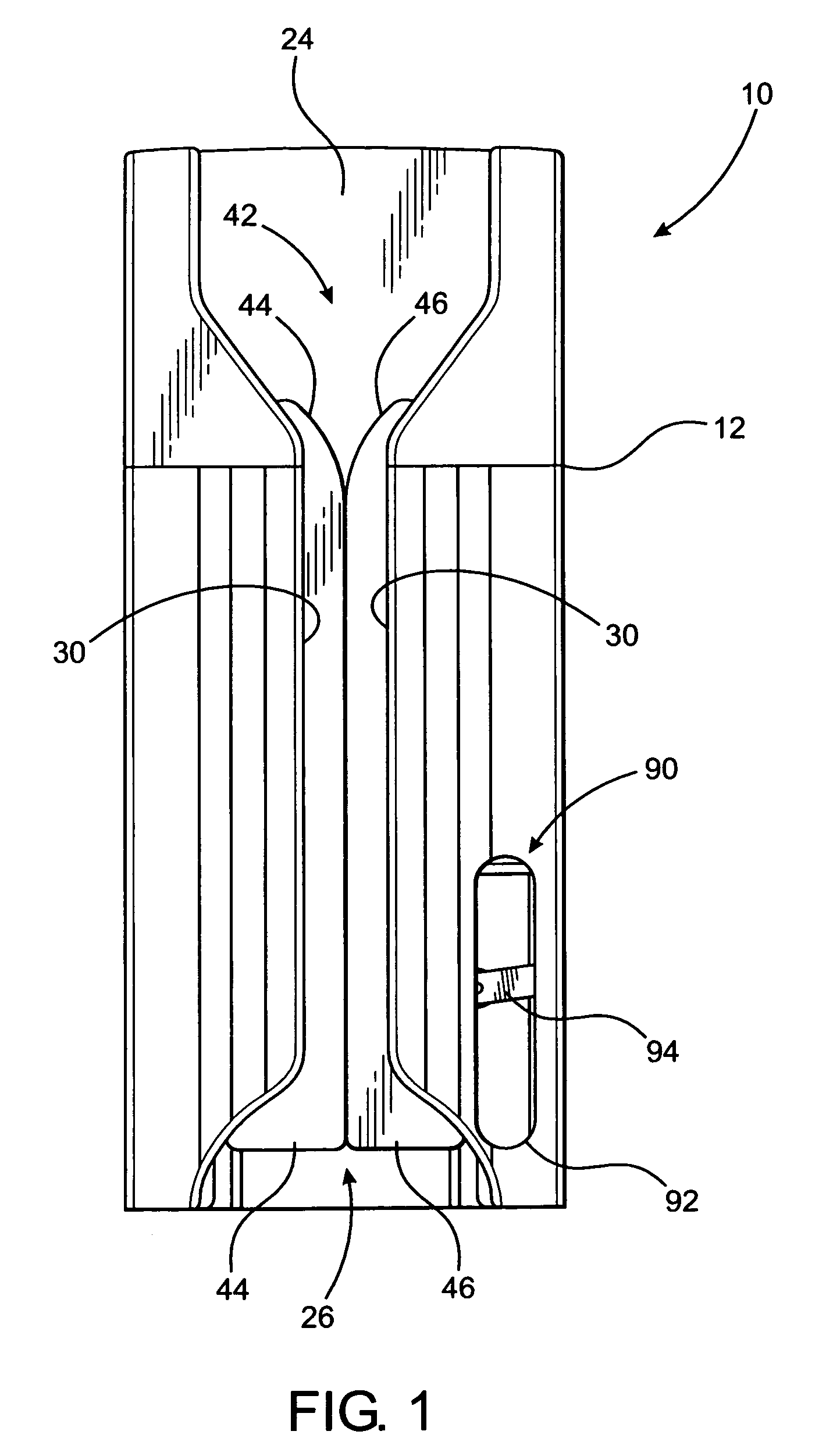
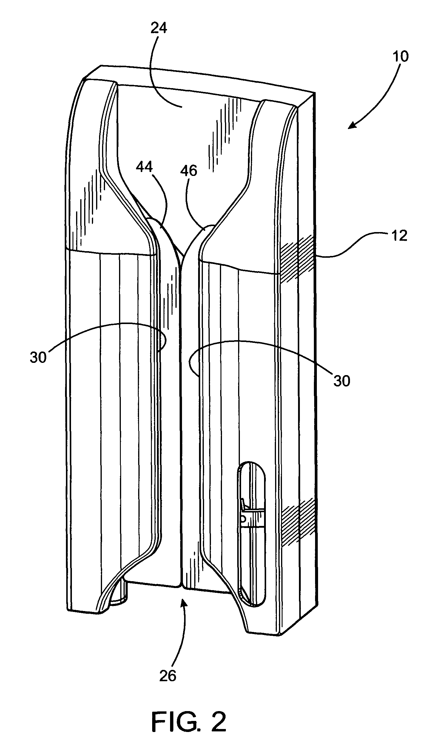
[0053]As shown in the accompanying drawings, the present invention is directed to a cleaning assembly 10 for the head of a stethoscope. The cleaning assembly 10 includes a housing 12 having a hollow interior of sufficient dimension and configuration to contain a plurality of operative components to be described in greater detail hereinafter. As also described, the cleaning assembly 10 is specifically structured to “clean” the diaphragm, supportive rim and other exposed portions of the head which are brought into direct contact with a patient's body. More specifically, the head portion 14 as represented in FIG. 10 includes a diaphragm 16 and supportive and / or surrounding rim portion 18 generally associated with an exposed face or patient contacting portion 20 of the stethoscope head 14. Additional features relating to the manipulation or placement of the head 14 comprise the structuring of the housing 12, as well as other operative components associated therewith, which facilitates a...


PUM

PropertyMeasurementUnit
voltage electricityaaaaaaaaaa
lengthaaaaaaaaaa
flexibleaaaaaaaaaa

Abstract

An assembly structured to clean the head portion of a stethoscope comprising a housing including a path of travel along which the head portion passes during cleaning. A supply of cleaning fluid is associated with a dispenser assembly which is cooperatively disposed relative to an activating assembly. The activating assembly is manually operated due to moveable engagement with the head portion as it travels along the path of travel. The activating assembly is thereby operatively positioned to activate the dispenser assembly when engaged by the head portion as it passes along the path of travel. The dispenser assembly delivers the cleaning fluid to an applicator assembly which distributes the cleaning fluid to the head portion and facilitates the cleaning thereof and removal of excess cleaning fluid there from.

Description

CLAIM OF PRIORITY[0001]The present application is a Continuation-In-Part application of previously filed, application having Ser. No. 12 / 079,077 filed on Mar. 24, 2008, now U.S. Pat. No. 7,503,335 which is a Continuation-In-Part of U.S. patent application having Ser. No. 11 / 728,207, filed on Mar. 23, 2007, which matured into U.S. Pat. No. 7,406,973 on Aug. 5, 2008, all of which are incorporated herein in their entirety by reference.BACKGROUND OF THE INVENTION[0002]1. Field of the Invention[0003]This invention is directed to an assembly structured to clean the head portion of a stethoscope comprising a housing including a path of travel along which the head portion passes during cleaning. A supply of cleaning fluid is associated with a dispenser assembly which is cooperatively disposed relative to an activating assembly. The activating assembly is operatively positioned to activate the dispenser assembly when engaged by the head portion as it passes along the path of travel. The disp...

Claims


Application Information

Patent Timeline
Patent Type & Authority Patents(United States)
IPC IPC(8): B43K29/00B43K1/00B05C1/00A47L13/12A47L1/08A47L1/02B08B9/00B08B3/12A61B7/02A61L2/00A61L9/00
CPCA61B19/34A61L2/18A61B7/02A61B90/70
Inventor PERLMAN, MICHAELSELLERS, JAMES M.RUBIN, KEITHCARDINALI, MATHEWCOLE, MICHAEL R.PERLMAN, SIDNEY
Owner SEEDLINGS LIFE SCI VENTURES
Learn More