
Computer-implemented method and computerized device for testing a technical system

a technology of computerized devices and computer programs, applied in the direction of testing/monitoring control systems, instruments, process and machine control, etc., can solve the problems of additional effort, loss of information, and inability to directly connect safety analyses,

Pending Publication Date: 2022-03-03
SIEMENS AG
View PDF0 Cites 0 Cited by
  • Summary
  • Abstract
  • Description
  • Claims
  • Application Information

AI Technical Summary

Benefits of technology

The patent text describes a method for creating a safety model that can be used to test the functionality of a technical system. This safety model is connected to a test model, which helps to automatically generate test parameters and new test cases. This approach increases efficiency and effectiveness of the testing process compared to a conventional, manual approach. The safety model also helps to define the expected system behavior, which is important for ensuring safety and reliability. Additionally, the method allows for the generation of test scenarios covering different fault scenarios, which can be used to create a fully automated test suite. Overall, this method helps to improve the efficiency and accuracy of testing processes.

Problems solved by technology

However, the safety analyses are usually not connected directly to the system design and test environments.
This disconnect between the different engineering disciplines leads to a loss of information, to additional effort required to specify tests or test cases and the check if all measures realized to prevent hazards have been tested.
However, safety models conventionally consisting of manual analyses performed by safety together with system experts are not integrated with system or test models.
This manual approach takes a lot of effort, is limited in scope, as the tests have to be defined manually.
As systems get more and more complex, model-based approaches are used in the system development, but also for testing and safety it is difficult to conventionally evaluate if the defined tests cover the relevant safety functionality adequately.
A conventional problem with tests is not only the definition of the input values, but also the expected system behavior.
For example, if the technical system is a railway and the safety-relevant functionality is decelerating the railway to a certain velocity within a certain time period, then a violation of said safety-relevant functionality may be if the railway cannot be decelerated to said certain velocity within the certain time period.

Method used


Image

  • Computer-implemented method and computerized device for testing a technical system
  • Computer-implemented method and computerized device for testing a technical system
  • Computer-implemented method and computerized device for testing a technical system

Examples


Embodiment Construction

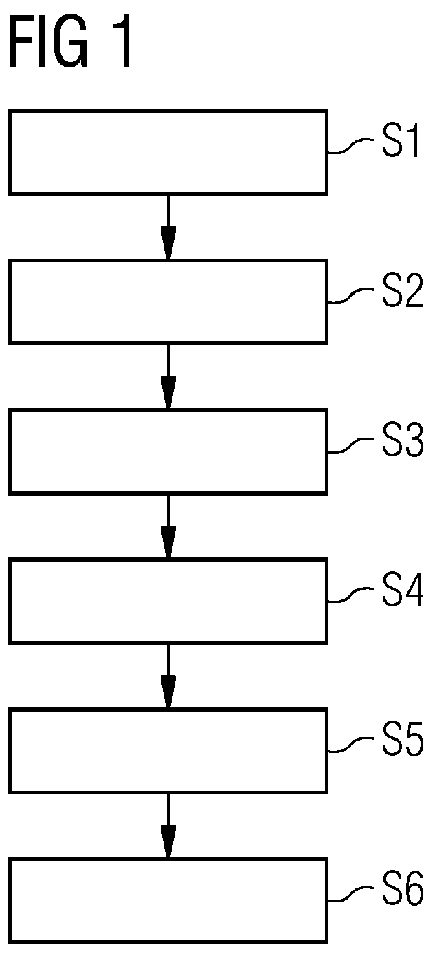
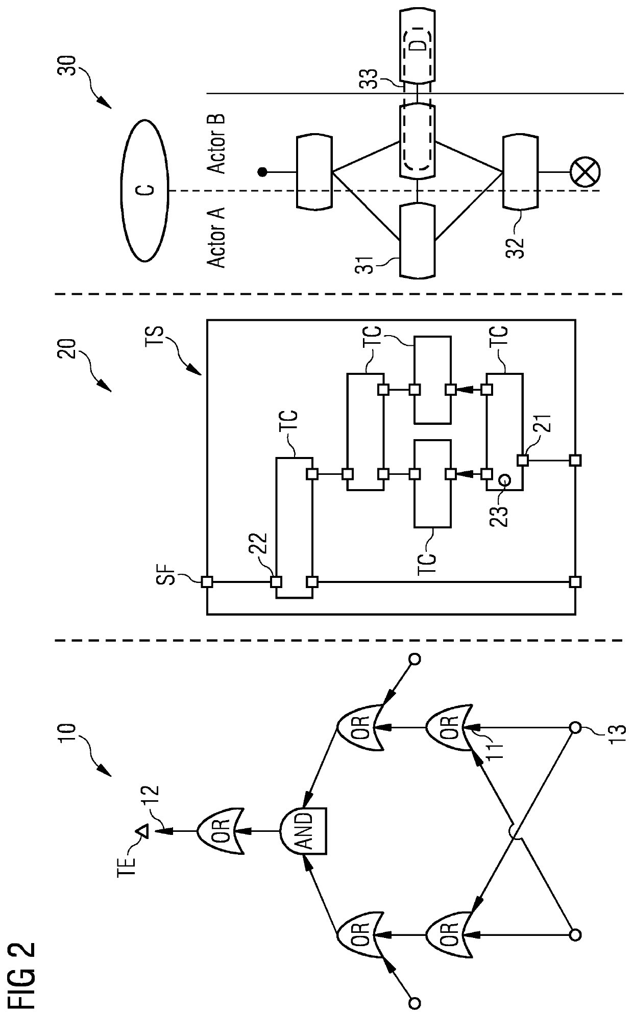
[0095]FIG. 1 depicts a sequence of method steps of an embodiment of a computer-implemented method for testing a technical system TS. In FIG. 1, the method steps are designated with S1-S6. In the following, FIG. 1 is discussed referring to FIG. 2.

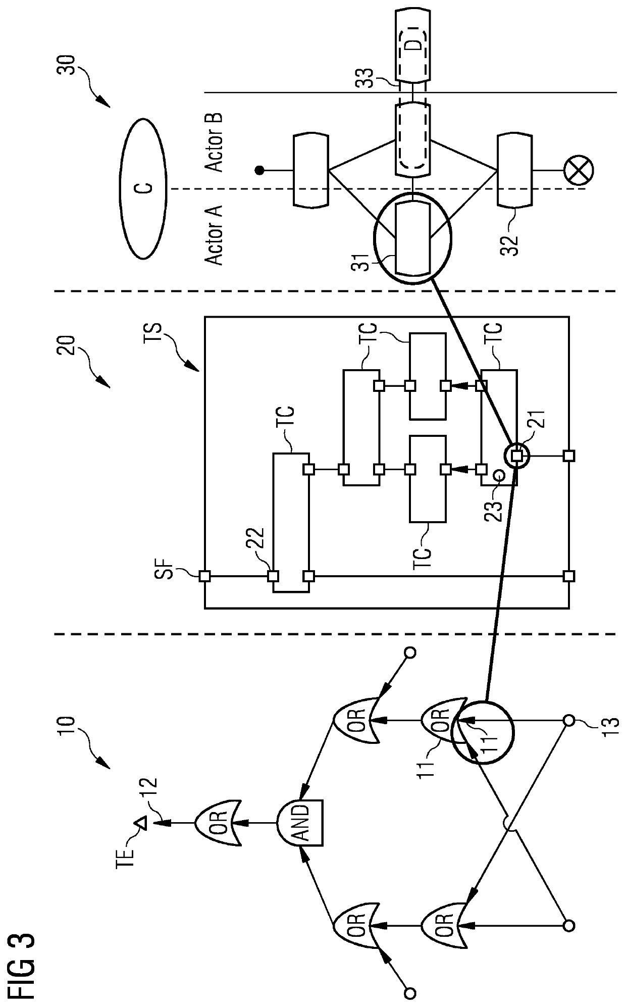
[0096]In this regard, the left part of FIG. 2 shows an example of a safety model 10 for the technical system TS, the middle part of FIG. 2 shows an example of a system model 20 for the technical system TS and the right part of FIG. 2 shows an example of a test model 30 for the technical system TS.

[0097]The technical system TS may be a safety-critical system, for example used in an application domain of embedded systems, such as aerospace, railway, health care, automotive or industrial automation. The technical system TS includes a plurality of technical components TC, for example including actors, sensors and / or receivers.

[0098]As indicated above, the method of FIG. 1 includes the method steps S1-S6: In step S1, a safety model 10 modeling a ...


PUM


Abstract

The computer-implemented method for testing a technical system having a plurality of technical components includes: providing a safety model modeling a safety relevant functionality of the technical system, providing a test model including test cases for testing the technical system, linking elements of the safety model with elements of the test model for enabling a tracing between the test cases of the test model and the safety-relevant functionality of the safety model, generating test parameters for at least one certain test case of the test cases and / or a new test case for the test model using the safety model linked to the test model, and testing the technical system using the certain test case and / or the new test case. Further, a computer program product, a computerized device and an arrangement having a technical system and a computerized device are provided.

Description

CROSS-REFERENCE TO RELATED APPLICATIONS[0001]This application claims priority to EP Application No. 20193284.5, having a filing date of Aug. 28, 2021, the entire contents of which are hereby incorporated by reference.FIELD OF TECHNOLOGY[0002]The following relates to a computer-implemented method and to a computer program product for testing a technical system having a plurality of technical components. The following further relates to a computerized device for testing a technical system having a plurality of technical components and to an arrangement comprising a technical system and such a computerized device for testing the technical system.BACKGROUND[0003]Testing a technical system may particularly include testing regarding functional behavior of the technical system as well as regarding safety of the technical system.[0004]For example, a technical system to be tested may be a safety-critical system or safety-relevant system. The importance of safety-critical systems in many appl...

Claims


Application Information

Patent Timeline
IPC IPC(8): G06F30/20G01M99/00
CPCG06F30/20G01M99/008G06F11/3684G06F11/3676G05B23/0248G05B23/0256G06F11/261G01R31/31835G06Q10/06G05B23/0283G06F11/008G06F11/079
Inventor ROTHBAUER, STEFANZELLER, MARCSTORCK, STEPHAN
Owner SIEMENS AG
Learn More