
Automatic screw feeding apparatus for power screwdriver

a technology of automatic screw feeding and power screwdriver, which is applied in the direction of apparatus for dispensing discrete objects, instruments, manufacturing tools, etc., can solve the problems of increasing delivery costs, time waste, and the inability to remove the moving guid

Inactive Publication Date: 2011-01-11
MOBILETRON ELECTRONICS
View PDF4 Cites 25 Cited by
  • Summary
  • Abstract
  • Description
  • Claims
  • Application Information

AI Technical Summary

Benefits of technology

[0010]The primary objective of the present invention is to provide an automatic screw feeding apparatus, which does not jam the screws while they are fed.
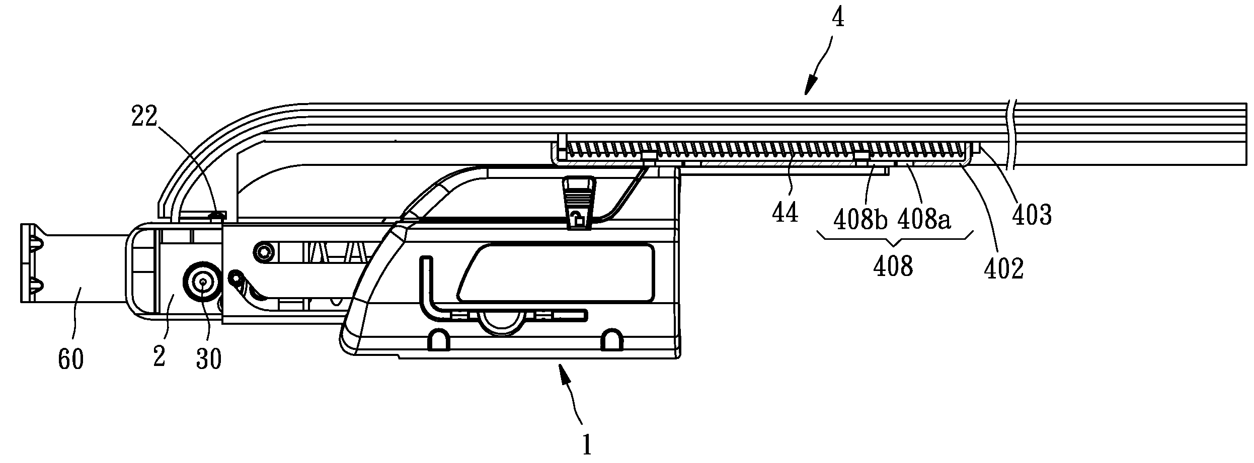
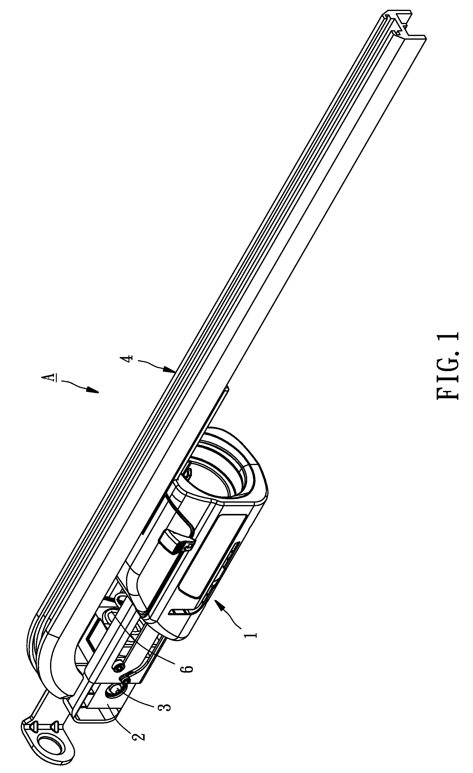
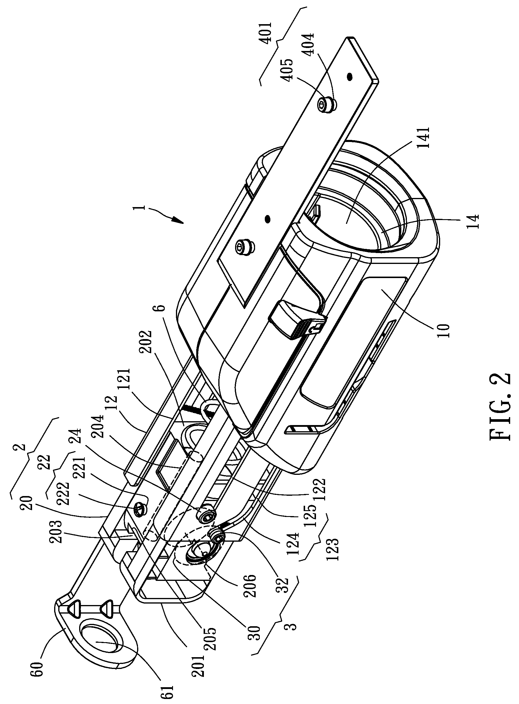
[0011]The foregoing objective of the present invention is attained by the automatic screw feeding apparatus composed of a base assembly, a slide assembly, a first spring, a screw carrier driving device, and a screw carrier guidance device. The base assembly is adapted for connection with a power screwdriver. The slide assembly is slidably mounted to the base assembly, movable forward and backward between a first position and a second position along a straight path. The slide assembly includes a passage having a first inlet and a first outlet. One end of a screw carrier can enter the passage from the first inlet and exit the passage from the first outlet. The first spring is mounted between the base assembly and the slide assembly for keeping the slide assembly at the first position. The screw carrier driving device is mounted to the slide assembly for driving a screw carrier having a part located in the passage to move along the passage for a fixed distance while the slide assembly is moved to the second position from the first position. The screw carrier guidance device includes a connection member, a guide member, and at least one second spring. The connection member is mounted to the base assembly. The guide member has a first end, a second end, and a guide groove. The guide groove defines a second inlet and a second outlet. The second inlet is located at the first end of the guide member. The second outlet is located at the second end of the guide member. One end of the screw carrier can enter the guide groove from the second inlet and exit the guide groove from the second outlet. The guide member is movable forward and backward between a third position and a fourth position of the connection member. When the guide member is located at the third position, the second outlet is located close to the first inlet of the slide assembly for facilitating one end of the screw carrier to smoothly enter the passage from the second outlet through the first inlet. The second spring is mounted between the guide member and the connection member for keeping the guide member located at the third position.
[0012]Because the second spring can push the guide member, the screw carrier, and a plurality of screws carried on the screw carrier from the fourth position to the third position, the load of the first spring can be lightened to prevent the fed screws from being jammed.
[0013]The secondary objective of the present invention is to provide an automatic screw feeding apparatus, which is conveniently portable for the user to lower the delivery cost.

Problems solved by technology

Because the front end of the movable guide is fixed to the slide body subassembly and the primary part of the movable guide is mostly covered by the housing portion, the movable guide cannot be detached unless a tool is used and a lot of time is spent.
In this way, the portable screw driving tool is too large to be conveniently portable for the user, also increasing the delivery cost.
In this way, the spring is heavily loaded to cause unsmooth movement of the slide body subassembly, the movable guide, the plastic strip, and the screws and even to cause regular failure while the sprocket drives the plastic strip to further jam the screws while they are fed.

Method used


Image

  • Automatic screw feeding apparatus for power screwdriver
  • Automatic screw feeding apparatus for power screwdriver
  • Automatic screw feeding apparatus for power screwdriver

Examples


first embodiment

[0044]Referring to FIG. 13, the screw carrier guidance device 5 is composed of a connection member 50, a guide member 52, and a spring 54. The connection member 50 includes two connection pieces 501, a connection base 502, and a guide bar 503. The connection pieces 501, the connection base 502, and the guide bar 503 are identical to those of the first embodiment, so that their detailed recitations are skipped.

[0045]The guide member 52 includes a guide rail 521, a coupling portion 522, and a base 523. The guide rail 521 has one end defined as a first end 521a of the guide member 52 and the other end thereof defined as a connection end 521b. The coupling portion 522 has one end connected with the connection end 521b of the guide rail 521 and the other end defined as a second end of the guide member 52. The guide rail 521 has a primary guide groove 521c. The coupling portion 522 has a secondary guide groove 522a for connection with and in communication with the primary guide groove 521...

second embodiment

[0049]Although the connection member 70 of the second embodiment is different from those of the aforementioned embodiments, they have the same effects.


PUM


Abstract

An automatic screw feeding apparatus includes a base assembly, a slide assembly, a first spring, a screw carrier driving device, and a screw carrier guidance device. The slide assembly is mounted to the base assembly, movable forward and backward between a first position and a second position along a straight path. The first spring is mounted between the base and slide assemblies for keeping the slide assembly at the first position. The screw carrier guidance device includes a connection member connected with the base assembly, a guide member mounted to the connection member and movable forward and backward between a third position and a fourth position, and a second spring mounted between the guide and connection members for keeping the guide member located at the third position. The second spring can greatly lighten the load of the first spring to prevent the fed screws from being jammed.

Description

BACKGROUND OF THE INVENTION[0001]1. Field of the Invention[0002]The present invention relates generally to power tools, and more particularly, to an automatic screw feeding apparatus for a power screwdriver.[0003]2. Description of the Related Art[0004]A conventional screw feeding apparatus is mounted to a power screwdriver. When a user is operating the power screwdriver to screw screws onto a workpiece, a screw belt carrying a bunch of screws is automatically driven for movement along a fixed path and then the screws are conveyed to a front side of a screwdriver bit of the power screwdriver in turn to be driven by the driver bit for screw with the workpiece. In this way, the user does not have to put the screws one by one to a working position by one hand and to maintain them in position for screw with the workpiece by the power screwdriver, thus greatly shortening the required working time. Besides, the user can operate the power screwdriver by two hands to increase more safety for...

Claims


Application Information

Patent Timeline
Patent Type & Authority Patents(United States)
IPC IPC(8): B25B23/04
CPCB25B21/00B25B23/06B25B23/04B25B23/045
Inventor HSU, MING-HUNG
Owner MOBILETRON ELECTRONICS
Learn More