
Tank wall and method and system for making

a technology of metal tanks and walls, applied in the direction of manufacturing tools, soldering devices, auxilary welding devices, etc., can solve the problems of large manual labor, unsuitable for producing tanks, and unsatisfactory alignment of metal strips, so as to prevent cracks in metal strips

Inactive Publication Date: 2011-01-11
COBRA TANKS
View PDF9 Cites 9 Cited by
  • Summary
  • Abstract
  • Description
  • Claims
  • Application Information

AI Technical Summary

Benefits of technology

"The invention is a method for making a circular metal tank from a long sheet of metal. The edges of the sheet are bent to create a helical roller track on the outside of the tank. The tank is then supported and rotated on rollers as it is being manufactured. This method makes it easier to align the metal sheet and improves the strength and seal of the tank. The bending process also helps to reinforce the tank walls and prevents cracks that could lead to leaks or compromise the tank's integrity."

Problems solved by technology

This method of assembly requires a large amount of manual labour, a complicated tank support structure, and is unsuitable for producing tanks for storage of liquids due to the massive number of bolt holes requiring hydraulic seals to prevent the leakage of any stored liquid.
This technique for tank fabrication suffers from the following disadvantages:a) satisfactory alignment of metal strips ahead of a butt welder is difficult;b) slight misalignment of the metal strips, especially for thinner metal thicknesses, can cause weak welds and / or leaks due to insufficient metal-to-metal contact; andc) there is no provision for reinforcement of metal strips to prevent their deformation (e.g. bulging due to pressure on lower metal strips in a tall liquid storage tank.
Lipp suffers from the following disadvantages:a) the tanks are unsuitable for storage of liquids since perfect hydraulic seals at the mechanical bends cannot be guaranteed;b) the method is unsuitable for hard-to-bend metals, especially for higher carbon steels, due to the severity of the bends and lack of stress relief (e.g. annealing) after bending resulting in potential metal cracking and subsequent loss of strength and hydraulic seals;c) the thickness of usable metal is limited due to the severity of the bends, which may result in cracking and subsequent loss of strength and hydraulic seals; andd) there are no reinforcing corrugations in the coils to prevent bulging, which is especially problematic since the thickness of the metal that may be used is limited, as discussed in point (c) above.

Method used


Image

  • Tank wall and method and system for making
  • Tank wall and method and system for making
  • Tank wall and method and system for making

Examples


Embodiment Construction

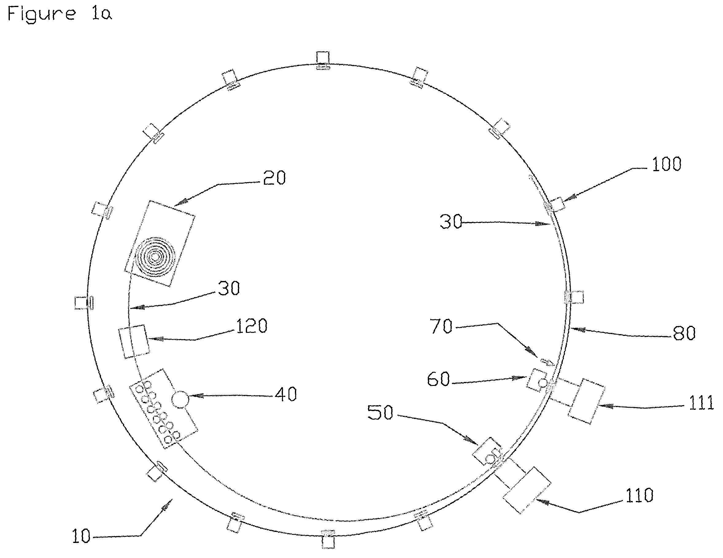
[0039]FIGS. 1a, 1b &1c show a top view of the cylindrical tank 10 being constructed according to the present invention. The major components are identified as follows:[0040]The Decoiler 20 unravels a coiled metal sheet 30 and feeds it into a Bender / Corrugator 40.[0041]The Bender / Corrugator 40 creates first and second bends to the longitudinal edges of the metal sheet and optionally imparts single or multiple waveform reinforcing corrugations along the length of the decoiled metal sheet 30.[0042]Welding Pre-aligner 50“gross” positions adjacent edges of metal sheet 30 after it exits the Bender / Corrugator 40 and ahead of the Welding Positioner 60.[0043]Welding Positioner 60“fine” positions adjacent edges of the metal sheet 30 after it exits the Welding Pre-Aligner 50 and before it enters the Welder Assembly 70.[0044]Welder Assembly 70 welds (e.g. by fillet weld) adjacent edges of the metal sheet 30.[0045]Support System 80 which is a structure having rollers and positioners (e.g. Weldin...


PUM

PropertyMeasurementUnit
angleaaaaaaaaaa
angleaaaaaaaaaa
widthaaaaaaaaaa

Abstract

A method for manufacturing a circular metal tank, from an elongated sheet of metal. The upper and lower longitudinal edges of the metal sheet are bent to produce a first “L” bend and a second “chair” bend, respectively. The sheet of metal is moved in a helical trajectory such that the second bend comes into proximity above the first bend. The second bend and the first bend are welded together such that the wall of the cylindrical tank is formed. Welding of the bends serves to stress relieve or anneal the bent metal, thereby preventing cracks in the metal which may result in leaks and / or compromise the structural integrity of the tank. The first and second bends additionally cooperate to form a helical roller track on the outside of the tank. The tank is supported and rotated about its longitudinal axis on a plurality of rollers that engage the roller track.

Description

RELATED APPLICATIONS[0001]This application claims the benefit of U.S. Provisional Patent Application 60 / 560,981, filed on Apr. 12, 2004.FIELD OF THE INVENTION[0002]This invention relates generally to the manufacture of circular metal tanks from steel coils shipped to site straight from the steel mill.BACKGROUND OF THE INVENTION[0003]The prior art describes a variety of methods for the construction of circular metal tanks used in storage of solids or liquids. For instance, U.S. Pat. No. 2,751,672, issued to Reed, describes the fabrication of circular tanks from a series of metal sheets which are bolted together. This method of assembly requires a large amount of manual labour, a complicated tank support structure, and is unsuitable for producing tanks for storage of liquids due to the massive number of bolt holes requiring hydraulic seals to prevent the leakage of any stored liquid.[0004]U.S. Pat. No. 4,121,747, issued to McFatter, describes the construction of circular storage tanks...

Claims


Application Information

Patent Timeline
Patent Type & Authority Patents(United States)
IPC IPC(8): B21C37/12B21C37/06B21D51/18B23K11/04B23K31/02B23K37/04
CPCB21C37/122B21D51/18B23K31/02B23K2201/12B23K2101/12
Inventor VANDERBEKEN, MARK
Owner COBRA TANKS
Learn More