Power state control for a desktop blade in a blade server system

a power state control and blade server technology, applied in computing, instruments, electric digital data processing, etc., can solve the problems of no convenient way to access the various other power states, no convenient way for remote users to conveniently manage many of the power state activities, current process, etc., and achieve the effect of minimal video compression

Active Publication Date: 2011-01-04
LENOVO GLOBAL TECH INT LTD
View PDF7 Cites 10 Cited by
  • Summary
  • Abstract
  • Description
  • Claims
  • Application Information

AI Technical Summary

Benefits of technology

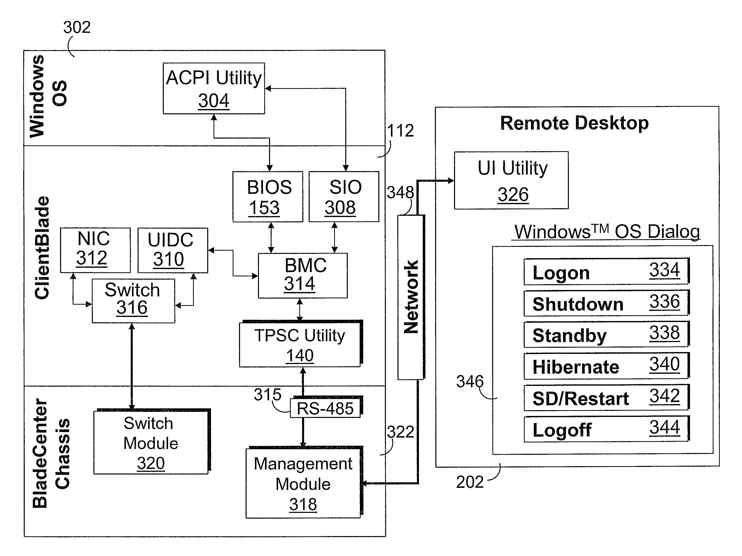
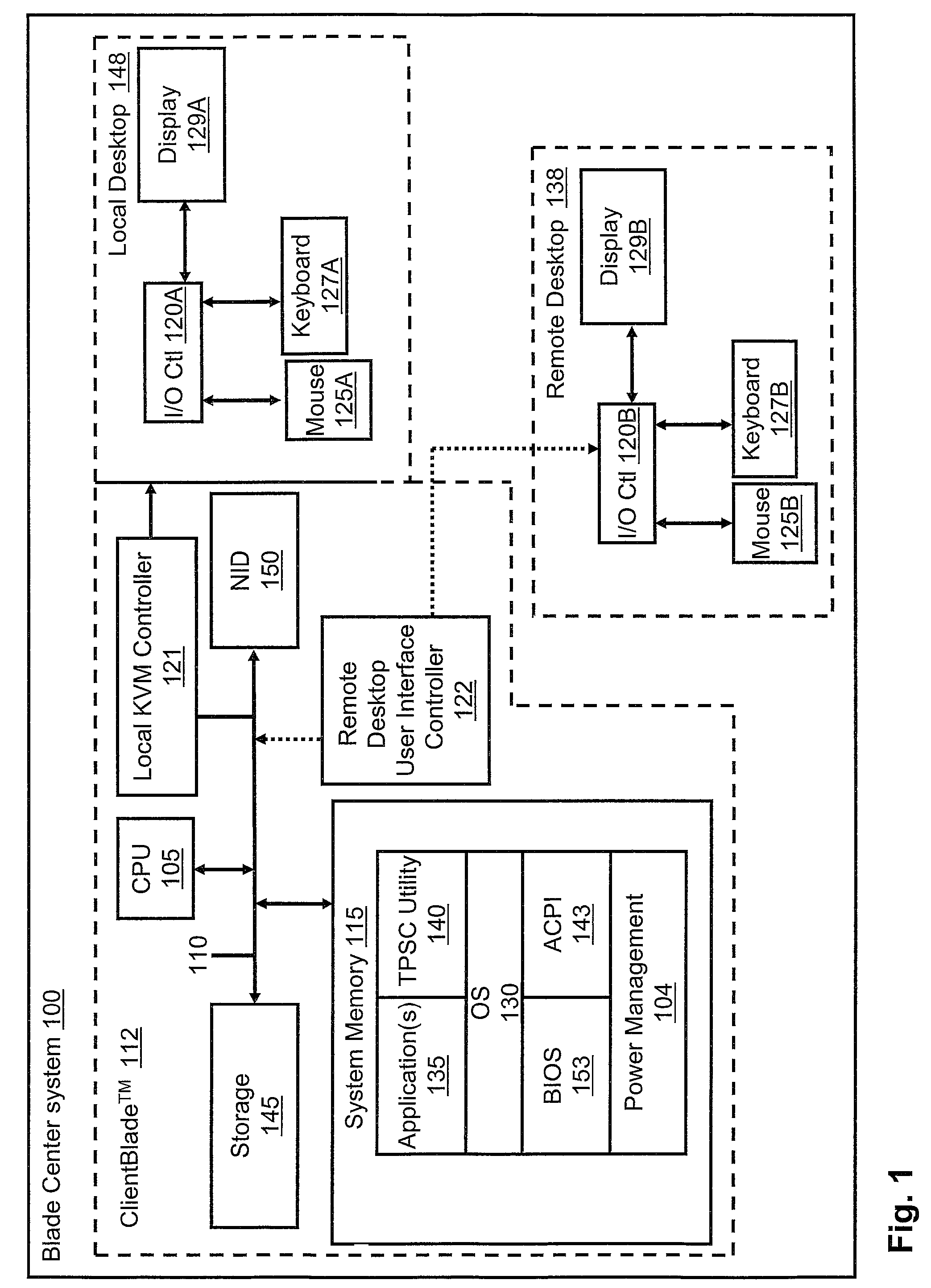
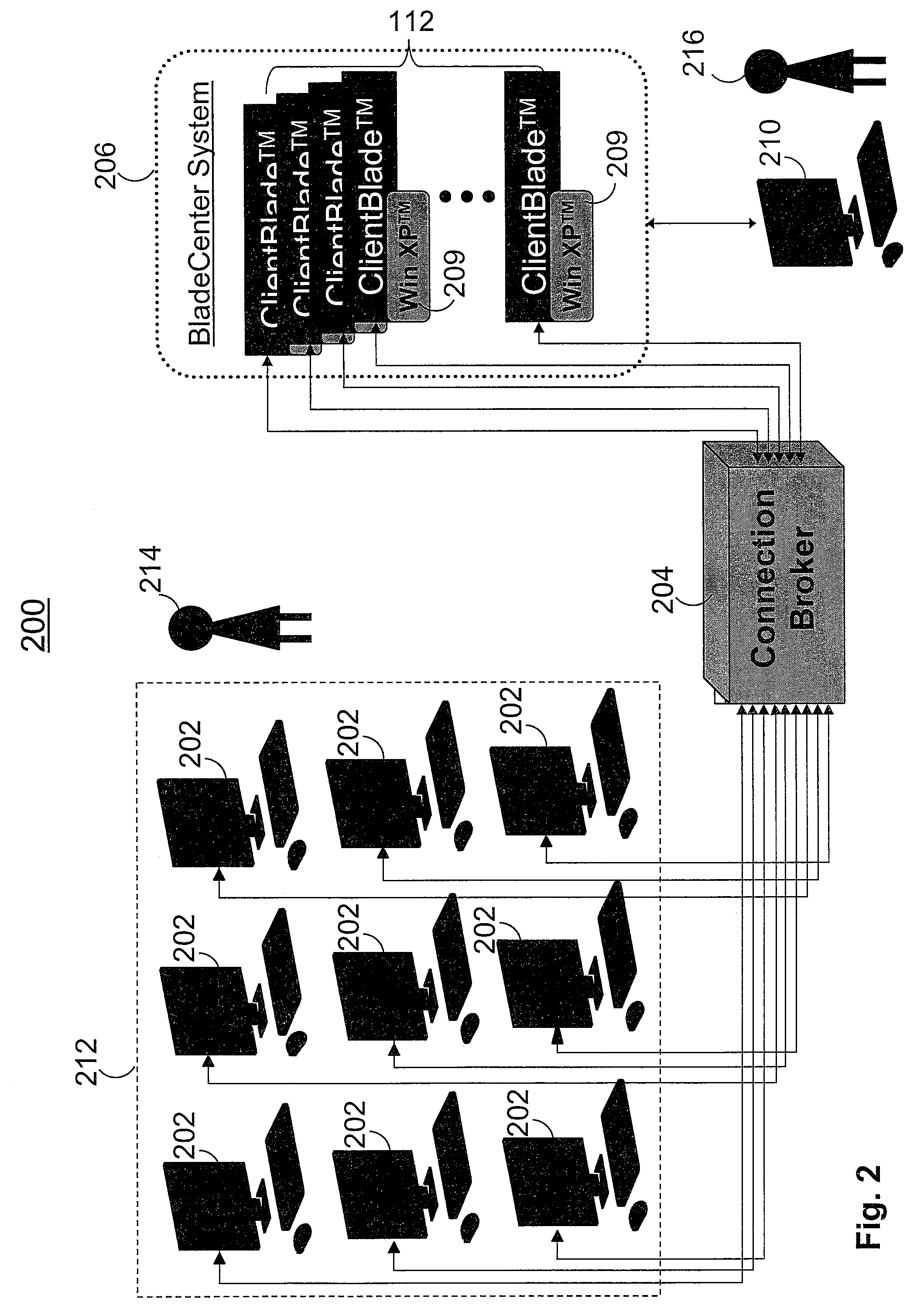
[0009]Disclosed is a method for enabling a remote user to control the different power states of a ClientBlade™ from a remote desktop environment. An end-user is authenticated and then permitted to control the different power states of the ClientBlade™ from a remote device. In one embodiment, the remote user's (device) connects his computer device (laptop or desktop) to the ClientBlade™ (at the Blade Center) via a Remote Desktop Protocol (RDP), which performs minimal video compression and provides an Ethernet connection back to the Blade Center. The user inputs a key sequence, which initiates a power state interface (or input screen). The power state interface allows the user to select one of several power states. Once the power state is selected, a TCP / IP packet is generated and transmitted from the computer device to the ClientBlade™. The packet invokes the selected power state at the ClientBlade™. Once the power state is activated, a completion message verifying the power state change is sent back to the end user's computer device. The end user is thus provided the ability to place the ClientBlade™ in either the hibernate or sleep state from any location on the network.
[0012]In another embodiment, a serial over LAN (SOL) connection is utilized to control the sleep and hibernate power states of the ClientBlade™. The SOL connection of the ClientBlade™ transmits data over a local area network (LAN), and may be utilized for remote ClientBlade™ power state control. SOL avoids the use of access cables from serial-connections and allows a remote user to manage the power states of the ClientBlade™ from any remote location with network access through the ClientBlade™ Ethernet interface. Power state signals sent through the Ethernet are transmitted to the baseboard management controller (BMC) of the ClientBlade™, which provides pulsed instruction to the power state hardware regulating the various power states of the ClientBlade™. In addition to the ability of the end user to regulate the on / off power state of the ClientBlade™, the end user may also control the sleep and hibernate power states through the SOL connection.

Problems solved by technology

One drawback to existing implementations of the ClientBlade™ environment is that the ClientBlade™ does not enable a remote user(s) to conveniently manage many of the power state activities of the ClientBlade™.
However, there is currently no convenient way to access the various other power states (e.g., sleep state and hibernate state).
Thus, while the on / off power state changes are supported, there are many disadvantages to the current process when considering the inaccessibility of an end user to controlling the other power states of the ClientBlade™.

Method used


Image

  • Power state control for a desktop blade in a blade server system
  • Power state control for a desktop blade in a blade server system
  • Power state control for a desktop blade in a blade server system

Examples


Embodiment Construction

[0009]Disclosed is a method for enabling a remote user to control the different power states of a ClientBlade™ from a remote desktop environment. An end-user is authenticated and then permitted to control the different power states of the ClientBlade™ from a remote device. In one embodiment, the remote user's (device) connects his computer device (laptop or desktop) to the ClientBlade™ (at the Blade Center) via a Remote Desktop Protocol (RDP), which performs minimal video compression and provides an Ethernet connection back to the Blade Center. The user inputs a key sequence, which initiates a power state interface (or input screen). The power state interface allows the user to select one of several power states. Once the power state is selected, a TCP / IP packet is generated and transmitted from the computer device to the ClientBlade™. The packet invokes the selected power state at the ClientBlade™. Once the power state is activated, a completion message verifying the power state ch...


PUM


Abstract

A method for controlling the different power states of a ClientBlade™ from a remote desktop environment is described. The remote user's (device) connects his computer device (laptop or desktop) to the ClientBlade™ (at the Blade Center) via a Remote Desktop Protocol (RDP), which performs minimal video compression and provides an Ethernet connection back to the Blade Center. The user inputs a pre-defined key sequence, which initiates a power state interface (or input screen). The power state interface allows the user to select one of several power states. Once the power state is selected, a TCP / IP packet is generated and transmitted from the computer device to the ClientBlade™. The packet invokes the selected power state at the ClientBlade™. Once the power state is activated, a completion message verifying the power state change is sent back to the end user's computer device.

Description

RELATED APPLICATION & PRIORITY CLAIM[0001]The present invention is a continuation-in-part of U.S. patent application Ser. No. 11 / 616,501. The invention claims priority of the Dec. 27, 2006 filing date of the related application.BACKGROUND OF THE INVENTION[0002]1. Technical Field[0003]The present invention generally relates to computer systems and in particular to control of power states in computer systems. Still more particularly, the present invention relates to a method, system, and data processing system configuration that enable control of the power states in a BladeCenter™ environment.[0004]2. Description of the Related Art[0005]The need for more efficient processing systems has lead to the growth of multi-component computer systems. These computer systems often include components such as servers, hard drives, and peripheral devices stored in vertical racks, integrated into a freestanding chassis device. Also, as enterprises grow, requiring more computer power and less space c...

Claims


Application Information

Patent Timeline
Patent Type & Authority Patents(United States)
IPC IPC(8): G06F1/00
CPCG06F1/3209
Inventor BOZEK, JAMES J.ONO, MAKOTOSUFFERN, EDWARD S.
Owner LENOVO GLOBAL TECH INT LTD
Why Eureka
Try Eureka