Method of Power State Control for a ClientbladeTM in a BladecenterTM System
a power state control and bladecentertm technology, applied in the field of computer systems, can solve the problems of no convenient way to access the various other power states, no convenient way for remote users to conveniently manage many of the power state activities, and current process, and achieve the effect of minimal video compression
- Summary
- Abstract
- Description
- Claims
- Application Information
AI Technical Summary
Benefits of technology
Problems solved by technology
Method used
Image

Examples
Embodiment Construction
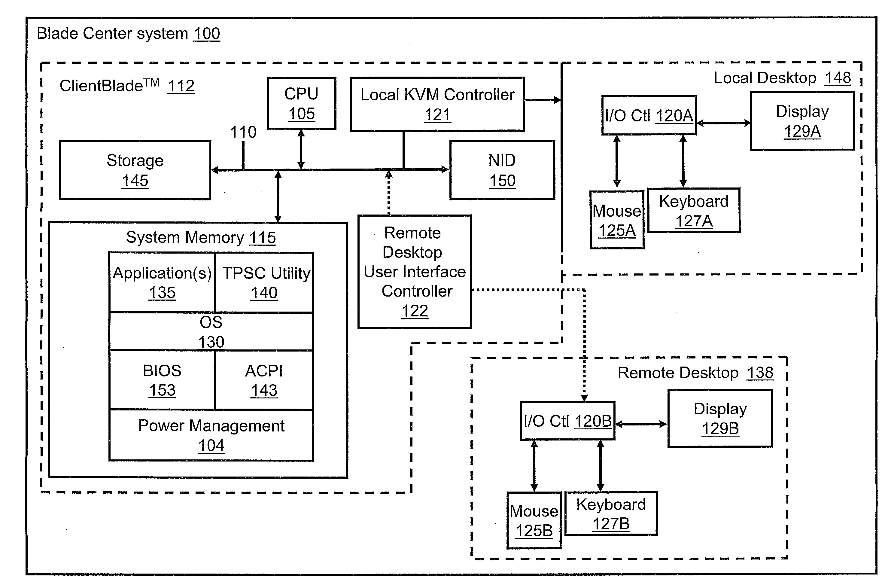
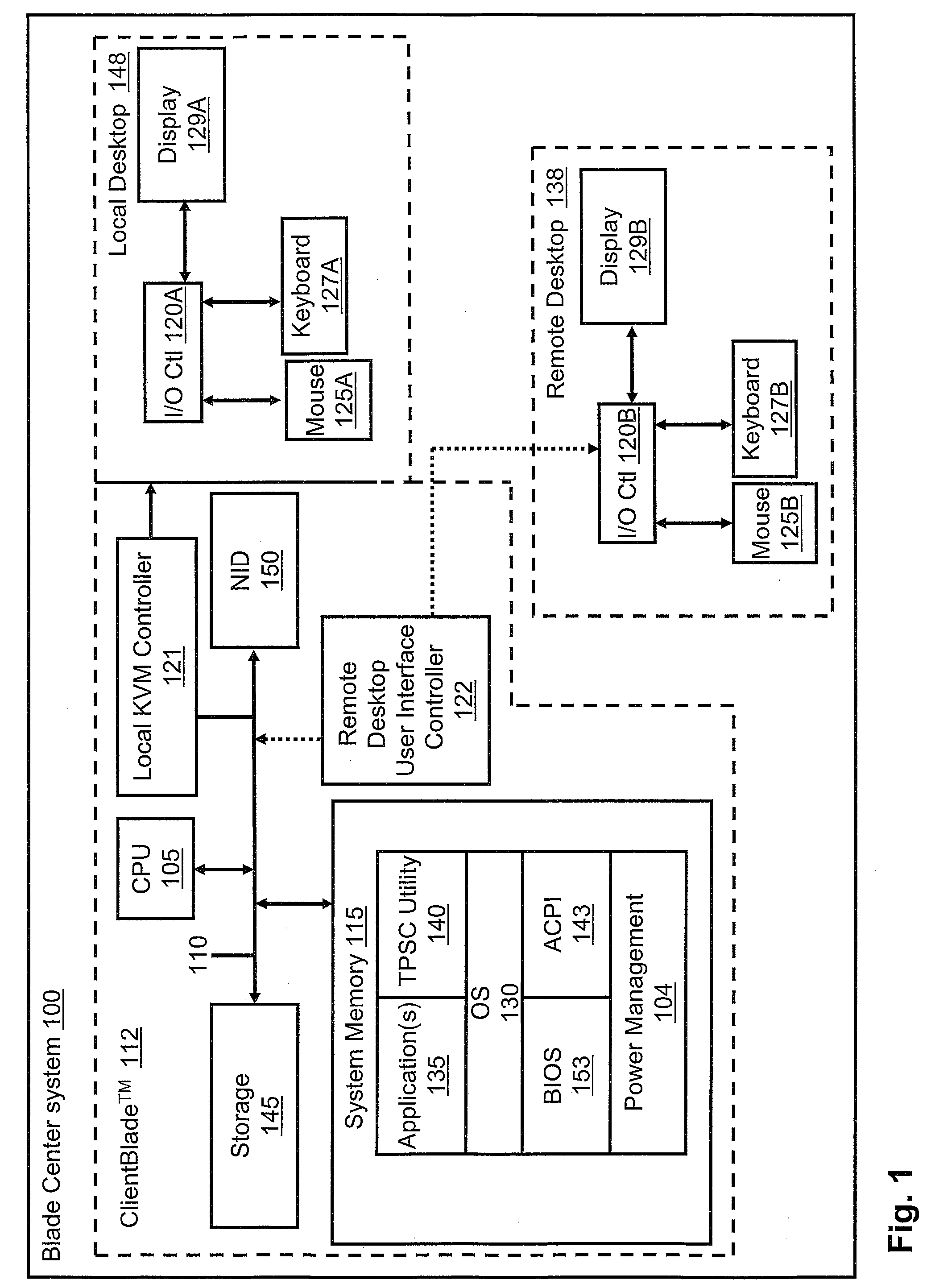
[0009]Disclosed is a method for enabling a remote user to control the different power states of a ClientBlade™ from a remote desktop environment. An end-user is authenticated and then permitted to control the different power states of the ClientBlade™ from a remote device. In one embodiment, the remote user's (device) connects his computer device (laptop or desktop) to the ClientBlade™ (at the Blade Center) via a Remote Desktop Protocol (RDP), which performs minimal video compression and provides an Ethernet connection back to the Blade Center. The user inputs a key sequence, which initiates a power state interface (or input screen). The power state interface allows the user to select one of several power states. Once the power state is selected, a TCP / IP packet is generated and transmitted from the computer device to the ClientBlade™. The packet invokes the selected power state at the ClientBlade™. Once the power state is activated, a completion message verifying the power state ch...
PUM
 Abstract
Description
Claims
Application Information
 - R&D
- Intellectual Property
- Life Sciences
- Materials
- Tech Scout
- Unparalleled Data Quality
- Higher Quality Content
- 60% Fewer Hallucinations
Browse by: Latest US Patents, China's latest patents, Technical Efficacy Thesaurus, Application Domain, Technology Topic, Popular Technical Reports.
© 2025 PatSnap. All rights reserved.Legal|Privacy policy|Modern Slavery Act Transparency Statement|Sitemap|About US| Contact US: help@patsnap.com