
Signal detection in OFDM system

a radio receiver and signal detection technology, applied in the field of signal processing carried out in the radio receiver, can solve the problems of increasing the complexity, cost and affecting the operation the power level of the receiver is very low, so as to reduce the power consumption of the radio receiver, reduce the number of operations, and reduce the hardware size

Active Publication Date: 2011-01-04
NOKIA TECHNOLOGLES OY
View PDF91 Cites 7 Cited by
  • Summary
  • Abstract
  • Description
  • Claims
  • Application Information

AI Technical Summary

Benefits of technology

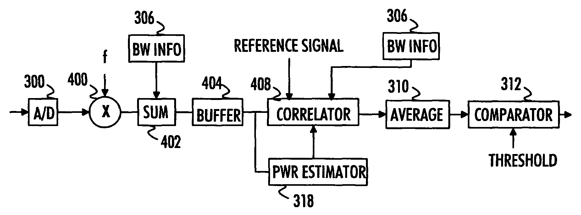
The invention provides an improved solution for signal detection in a radio receiver. It involves receiving a radio signal, converting it into a digitized signal, and calculating a sample shift value based on the known bandwidth of the desired signal and the total bandwidth of the received signal. The digitized signal is then compared with a reference signal with different sample shifts, and the result of the comparison is used to determine if the received signal is the desired signal. This method allows for more accurate signal detection with smaller hardware and fewer operations.

Problems solved by technology

The synchronization or pilot signal may be attenuated due to fading caused by a radio channel and, thus, it may arrive at a very low power level at the receiver.
Since the pilot signal represents only a fraction of the total bandwidth of the multicarrier signal, processing the pilot signal with the sample rate resulting from the A / D conversion results in unnecessary calculations and in large memory sizes.
This increases the complexity, cost, and power consumption of the radio receiver.

Method used


Image

  • Signal detection in OFDM system
  • Signal detection in OFDM system
  • Signal detection in OFDM system

Examples


Embodiment Construction

[0024]With reference to FIG. 1, examine an example of a communication system to which embodiments of the invention can be applied. The communication system may be a mobile communication system, such as a Universal Mobile Telecommunications system (UMTS). The mobile communication system may provide high-speed packet data services to mobile stations located within the coverage area of the system. Such a service may be, for example, a High-Speed Downlink Packet Access (HSDPA) service. Alternatively, the communication system may comprise two independent communication devices, for example two mobile phones communicating with each other wirelessly. The communication system may utilize a multicarrier data transmission scheme, such as Orthogonal Frequency Division Multiplexing (OFDM).

[0025]With reference to FIG. 1, examine an example of a structure of a radio receiver 100 to which embodiments of the invention can be applied. The radio receiver 100 in FIG. 1 is a radio receiver 100 capable o...


PUM


Abstract

A solution for signal detection in a radio receiver receiving multicarrier signals is disclosed. According to the provided solution, the radio receiver receives a radio signal and converts the received radio signal into digital samples. Since a desired signal being detected occupies only a portion of subcarriers of a signal the radio receiver is configured to receive, the received signal is heavily oversampled. A detection procedure may be simplified by utilizing this oversampling. A relation between the known total bandwidth of the desired signal and the total bandwidth of the received radio signal may be calculated, and utilized in the actual signal detection. The signal detection is based on sliding correlation in which the samples of the received signal are correlated with a reference signal with different phase shifts between the two signals. As the result of the correlation, the received signal is determined to be either the desired signal or noise.

Description

FIELD[0001]The invention relates generally to signal processing carried out in a radio receiver, and particularly to signal detection in a radio receiver capable of receiving and processing signals transmitted according to a multicarrier data transmission scheme.BACKGROUND[0002]Multicarrier data transmission schemes have been widely studied and, to some degree, employed as high-speed wireless data transmission schemes between two independent communication devices or in wireless telecommunication systems. Such multicarrier data transmission schemes include, for example, an Orthogonal Frequency Division Multiplexing (OFDM) scheme. In multicarrier systems, several data symbols are typically transmitted in parallel on a plurality of subcarriers. In order to enable data transmission between a transmitter and a receiver, the receiver must be able to detect a given synchronization or pilot signal transmitted by the transmitter. The synchronization or pilot signal may be attenuated due to f...

Claims


Application Information

Patent Timeline
Patent Type & Authority Patents(United States)
IPC IPC(8): H03K9/00
CPCH04L27/2655H04L27/2675H04L27/261
Inventor JANSEN, KAJ
Owner NOKIA TECHNOLOGLES OY
Learn More