
Guide, assembled guide and device for conditioning products displaceable along a guide track

a technology of assembled guides and conditioning products, which is applied in the direction of conveyor parts, drying machines with progressive movements, drying machines, etc., can solve the problems of uncontrollable orientation of the plastic guide parts (guide profiles) relative, obviating the controllable orientation of the guide profile, etc., to prevent the build-up of stress parallel to the guide surface, the effect of sufficient strength of the plastic guide profil

Inactive Publication Date: 2010-12-28
STORK TOWNSEND BV
View PDF18 Cites 1 Cited by
  • Summary
  • Abstract
  • Description
  • Claims
  • Application Information

AI Technical Summary

Benefits of technology

[0005]In order to also control the orientation of the guide profile (particularly in directions other than the longitudinal direction of the guide profile) as well as possible at the position where it supports freely on the support structure, in a preferred variant the guide profile is provided with a three-dimensional contact surface, and / or the support structure is provided with a three-dimensional contact surface at the position where the guide profile supports freely thereon. The ability to control the relative positioning of the guide profile and the support structure is increased by making use of a one or two-sided three-dimensional contact surface.
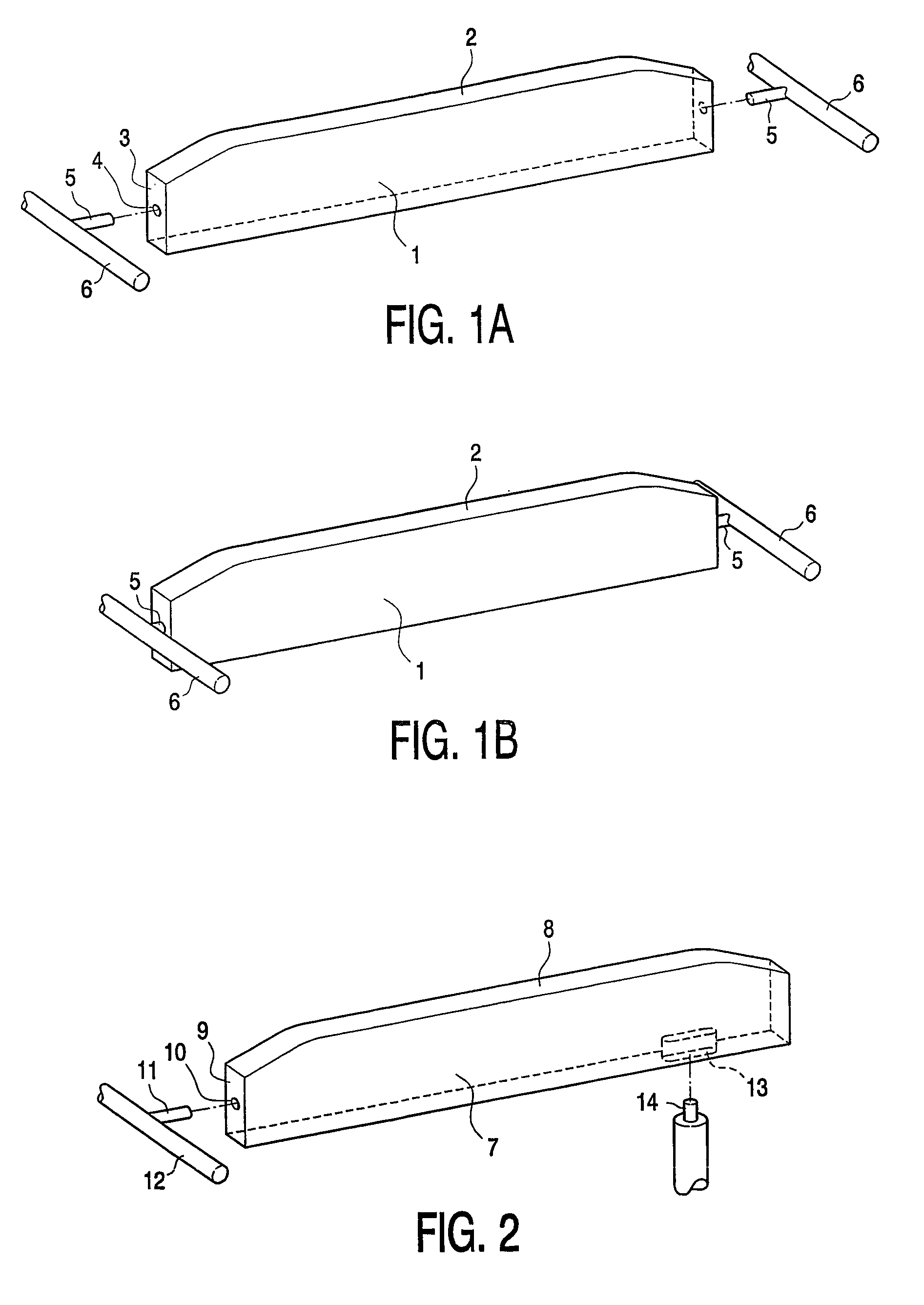
[0006]In a particular preferred variant, the free support of the guide profile on the support structure is formed by a recess in the guide profile in which an engaging part of the support structure engages close-fittingly and displaceably. A free space can herein be enclosed between the engaging part of the support structure and a part of the recess on the side remote from the engaging part, in which recess the engaging part is axially displaceable. This construction means that length variation of the plastic guide profile relative to the support structure does not result in build-up of stress in the plastic guide profile. The engaging part will after all displace in the guide profile when there is such a relative change in the dimensions. The result is that a controllable orientation of the plastic guide profile remains possible even in the case of considerable relative change in the dimensions of the guide profile and the support structure.
[0007]The orientation of the guide surface of the guide profile is particularly important for proper operation of the guide. It is therefore advantageous when the recess with the engaging part displaceable therein are formed such that the direction of displacement of the engaging part relative to the recess is at least substantially parallel to the guide surface of the plastic guide part. Build-up of stress parallel to the guide surface can in particular be prevented in this way.
[0009]It is found in practice that a sufficient strength of the plastic guide profile can be obtained at limited cost when the guide profile is manufactured from a high-molecular polyethylene. It will however generally be necessary here to give the plastic guide profile a relatively voluminous form (for instance beam-like). The support structure can be manufactured from metal.
[0010]In a preferred embodiment, the engaging part of the support structure and a recess co-acting therewith in the guide profile are at least substantially cylindrical. A cylinder shape can be manufactured relatively easily (drilling and turning for instance come to mind here) and has a surface which is relatively easy to clean and in which contaminants cannot adhere. Bolts, screws and such fastening means for fastening the profile are unnecessary. A stable support of the guide profile can be obtained when this latter is provided with engaging positions on opposite sides.
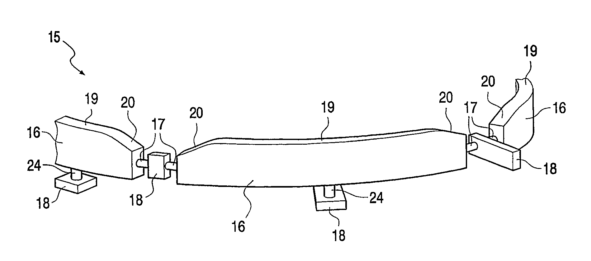
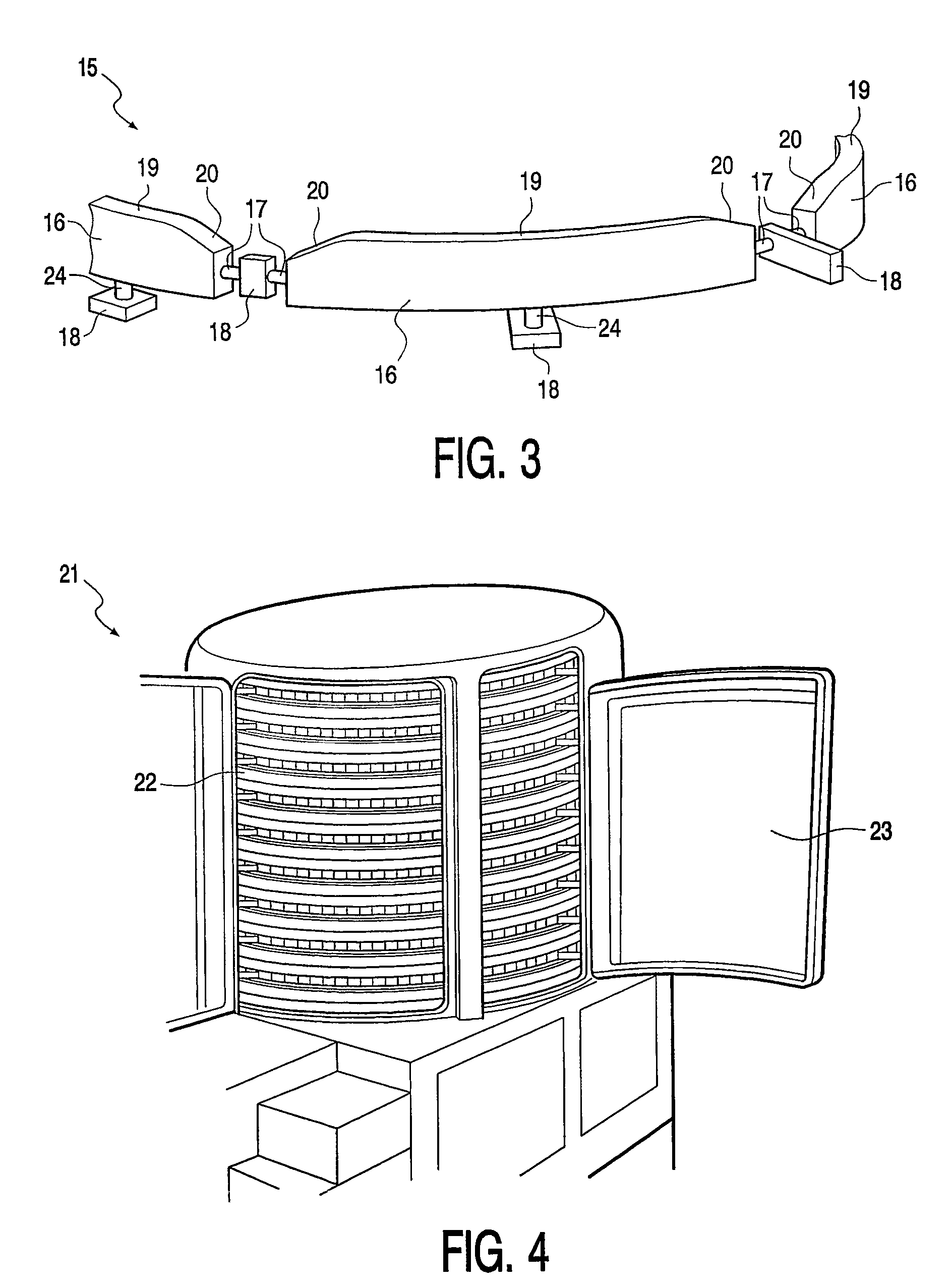
[0011]The invention also provides an assembled guide provided with a plurality of mutually connecting guides as described above, wherein a plurality of guide profiles are placed connecting with a gap to each other. The free spaces between the guide profiles are provided to compensate length changes in the individual guide profiles without affecting adjacent guide profiles. Advantageous results can be obtained with a gap which can be used for expansion of between 5 and 35 mm between a profile part and a support structure at atmospheric temperature, in particular when guide profiles are applied of high-molecular polyethylene with a length between 200 and 1200 mm. A plurality of profile parts can herein be engaged by a single support structure. This creates a direct connection between the individual profile parts. A particular variant of the assembled guide is provided with the plurality of profile parts which together form a helical guide track. Such a spiral-shaped guide track makes it possible to realize a long transport route in a limited space, which is advantageous for instance in towers for cooling, heating, smoking and / or otherwise conditioning products with a relatively long treatment time.

Problems solved by technology

A problem which can occur due to the small contact (in area) between the support structure, which will normally be manufactured from metal, and plastic is that the differing coefficients of expansion of the support structure and the plastic result in an uncontrollable orientation of the plastic guide part (guide profile) relative to the generally stationary support structure, particularly in conditions of changing temperatures.
However, the free support obviates this problem of controllable orientation of the guide profile as a result of only limited contact between support structure and plastic guide profile.

Method used


Image

  • Guide, assembled guide and device for conditioning products displaceable along a guide track
  • Guide, assembled guide and device for conditioning products displaceable along a guide track
  • Guide, assembled guide and device for conditioning products displaceable along a guide track

Examples


Embodiment Construction

[0020]FIG. 1A shows a beam-like plastic guide profile 1 provided with a guide surface 2. The end walls 3 of guide profile 1, only one of which is visible in the figure, are provided with cylindrical openings 4 arranged for co-action with cylindrical pins 5 carried by frame parts 6. Openings 4 are given a depth such that guide profile 1 can be pushed so far onto an associated pin 5 with one of the openings 4 that the opposite pin 5 can be pushed into the opening 4 co-acting therewith. A situation is thus obtained as shown in FIG. 1B; guide profile 1 is suspended from pins 5. Pins 5 herein have sufficient space in axial direction in openings 4 to compensate expansion (length increase) of guide profile 1. Conversely, pins 5 penetrate sufficiently far into openings 4 to compensate shrinkage (length decrease) of guide profile 1.

[0021]FIG. 2 shows an alternative embodiment variant of a plastic guide profile 7 provided with a guide surface 8 which is provided on an end wall 9 with a recess...


PUM


Abstract

The invention relates to a guide for supporting a displaceable object, comprising: a plastic guide profile (1, 7, 16, 30) and a support structure (6, 12, 18, 32) supporting the guide profile, characterized in that the guide profile is engaged at least at two spaced-apart positions by the support structure, at least one engaging position of which consists of a free support (4, 5, 10, 11, 13, 14, 33, 34) of the guide profile on the support structure such that the freely supporting side of the guide profile is displaceable relative to the support structure. The invention also relates to a device (21) for conditioning products displaceable along a guide track (22).

Description

BACKGROUND OF THE INVENTION[0001]The invention relates to a guide for supporting a displaceable object, comprising: a plastic guide profile, and a metal support structure supporting the guide profile. The invention also relates to an assembled guide provided with a plurality of guides according to the invention connecting onto each other. Finally, the invention further relates to a device for conditioning products displaceable along a guide track.[0002]In the displacement of products at a production location or a location where the products are processed, large-scale use is made of guides over which the products can slide directly or via a product carrier. In order to control the friction resistance and wear, use is made in the prior art of metal guides which are partially covered by plastic guide profiles. The drawbacks of such guides covered with plastic is that they are relatively costly and are in addition difficult to clean, particularly at the position where the plastic guide ...

Claims


Application Information

Patent Timeline
Patent Type & Authority Patents(United States)
IPC IPC(8): B65G15/62B65G21/22F26B15/26
CPCB65G21/22F26B15/26B65G2201/02B65G2207/24B65G21/18
Inventor BAKKER, JAAPVAN DE DUNGEN, WILHELMUS JOHANNES EVERARDUS MARIA
Owner STORK TOWNSEND BV
Learn More