


Quick Research
Generate reliable direction feasibility study reports for your R&D in just a few steps.

Technical Q&A
Discover and master advanced knowledge NOW. Basics, ideas, possibilities, all at once.

Find Solutions
As an expert in R&D theories, this can generate solutions to your technical problems instantly.

Evaluate Feasibility
Analyze your overall solution with one click, know your potential R&D risks in advance.

Monitor Landscape
Get weekly tech updates, stay abreast of the latest tech innovations and key insights.
Fuel reformer suppressing uneven temperature distribution in reforming element
a technology of reformer and fuel, applied in the field of fuel reformer, can solve the problems of uneven temperature distribution and temperature drop, and achieve the effect of suppressing uneven temperature distribution
- Summary
- Abstract
- Description
- Claims
- Application Information
AI Technical Summary
Benefits of technology
Problems solved by technology
Method used
Image

Examples
first embodiment
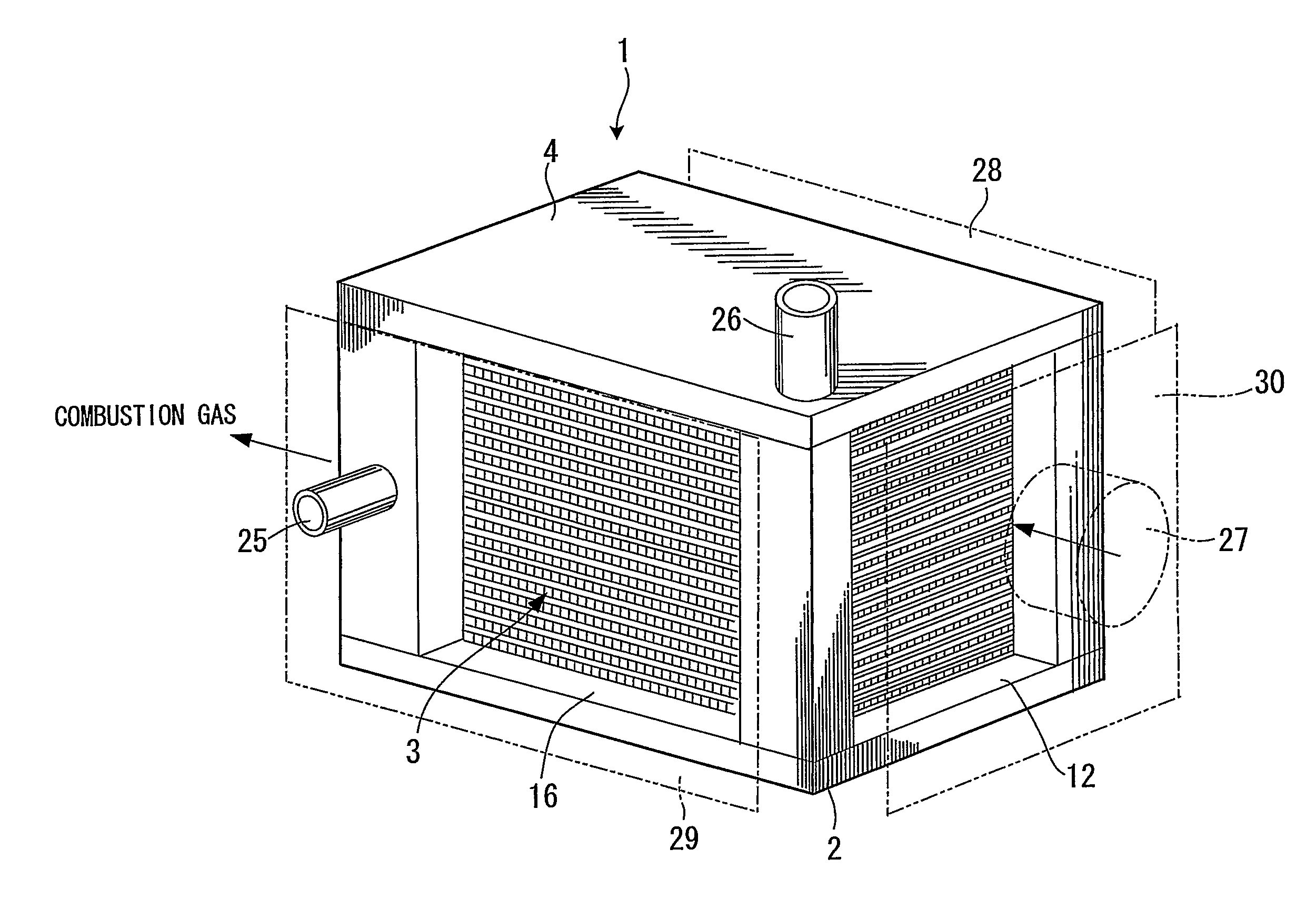
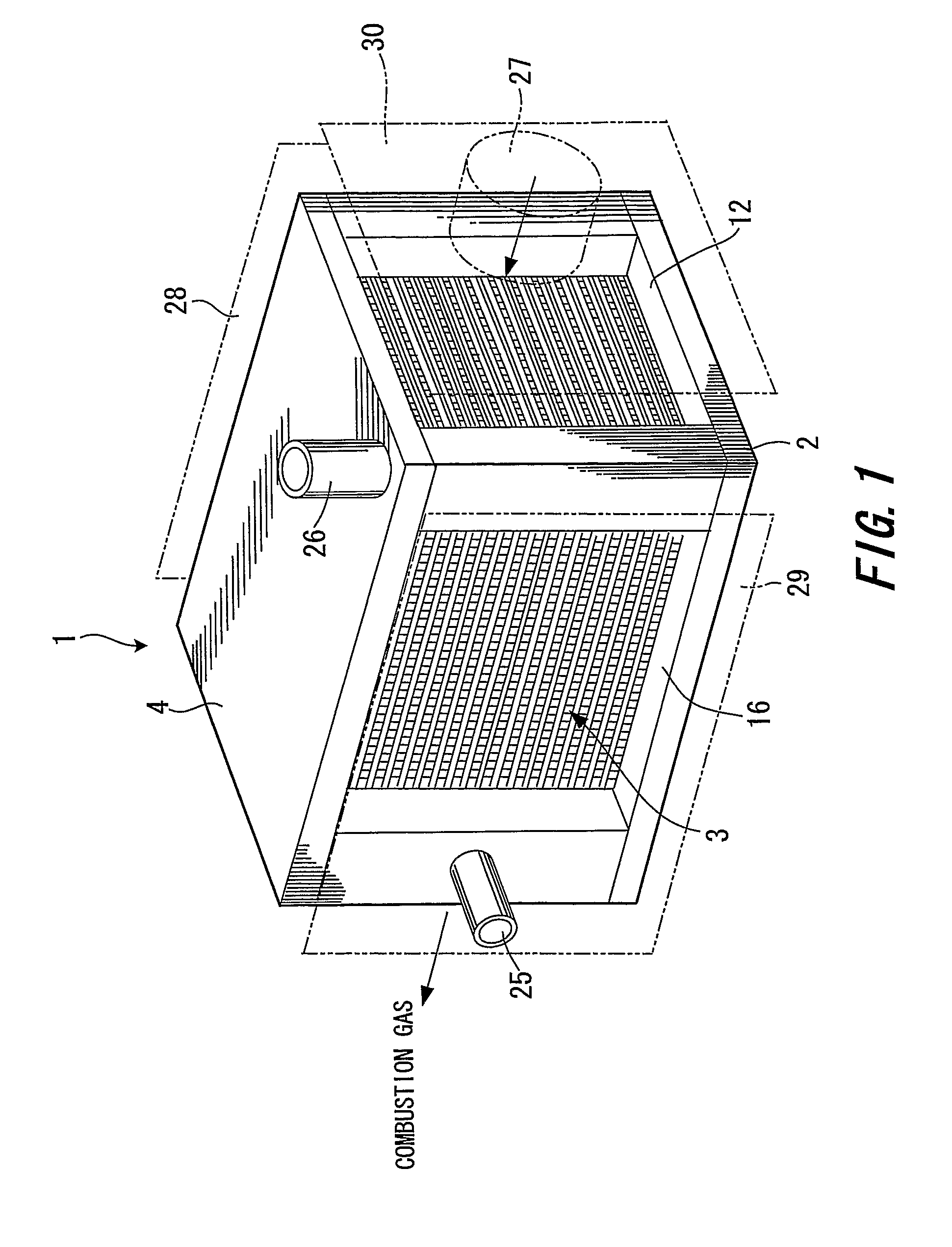
[0036]FIG. 1-FIG. 4 show a fuel reformer.
[0037]Referring to FIG. 1, a fuel reformer 1 comprises a lower end plate 2, plural fuel reforming units 3 laminated on the end plate 2, and an upper end plate 4. The fuel reformer 1 is tightened by a clamping means, not shown, in the lamination direction.
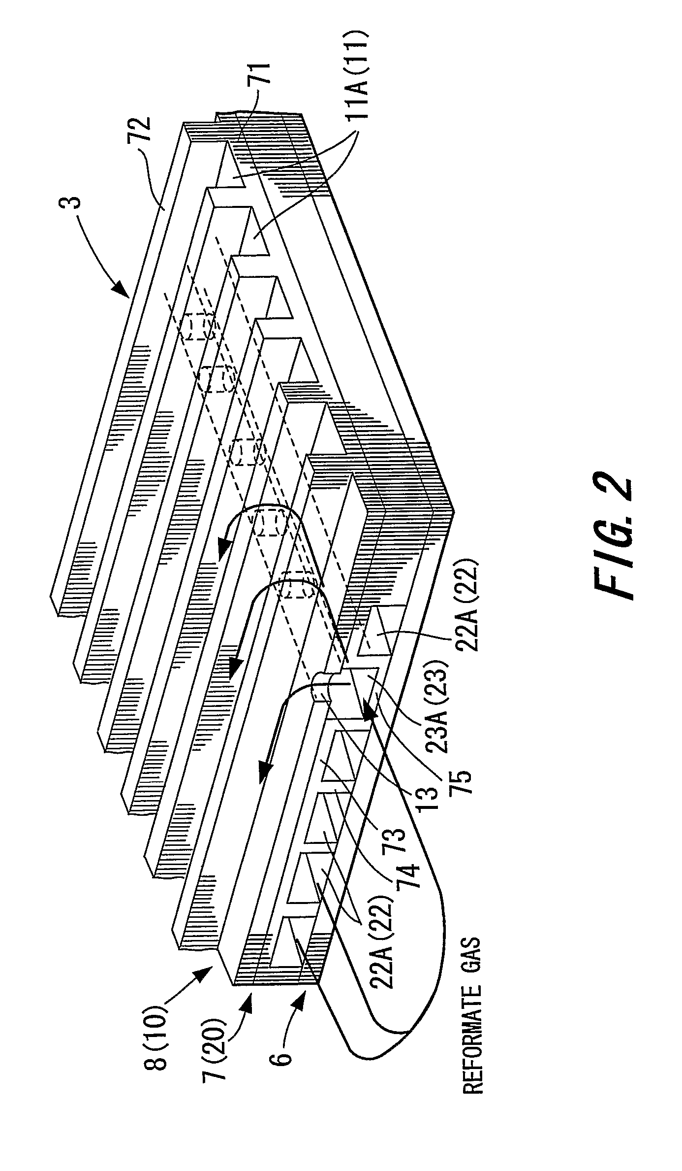
[0038]As shown in FIG. 2, the fuel reforming unit 3 is formed by laminating a plate-shaped reforming elements 7 and plate-shaped combustion elements 8 on a partition plate 6. In the combustion elements 8, combustible gas is burnt by oxygen in the air, and the adjacent reforming element is heated by the resultant heat. The combustion element 8 has a horizontal part 71 substantially perpendicular to the lamination direction, and a vertical part 72 (projecting part) extending essentially in the lamination direction from a horizontal part 71.
[0039]Referring to FIG. 3, the combustion element 8 has plural grooves 11A arranged parallel to one surface of a plate body 10 (member 10). The grooves 11A a...
second embodiment
[0110]In FIG. 21, the fuel injectors 31 are installed in the cover 29 facing the supply passages 23 which open towards the reformate discharge gas manifold 16A, in an identical way to that of the A fuel guide 32 is formed in the reformate discharge gas manifold 16A.
[0111]In the upper end plate 4, a hydrogen-rich gas outlet 56 is disposed in communication with the hydrogen-rich gas manifold 46, and in the cover 29 for the reformate discharge gas manifold 16A, the starting material inlet 25 in communication with the starting material manifold 14, is formed. The cover 29 is provided with fuel injectors 31 which inject additional fuel, but the fuel injectors 31 may be provided if required.
[0112]In addition to the advantages of the first embodiment and the second embodiment, this embodiment has the following advantages.
[0113]The fuel reformer 1 comprises the hydrogen separation membrane 54 adjacent to the reforming element 7, and the hydrogen-rich gas passage element 55 connected to the...
third embodiment
[0116]In FIG. 23, the combustion element 8 of this embodiment basically has an identical construction to that of the third embodiment, but the reformate gas manifold is omitted. A hydrogen-rich gas manifold 58 formed of a hole which does not communicate with other manifolds is newly installed on the side of the air manifold 12.
[0117]Referring to FIG. 24, the reforming elements 7 basically have an identical construction to that of the third embodiment. However, the reformate gas manifold is omitted, and the hydrogen-rich gas manifold 58 formed of a hole which does not communicate with other manifolds is newly installed on the side of the air manifold 12.
[0118]Referring to FIG. 25, the frame 49 of a hydrogen separation membrane element 59 comprises the starting material manifold 14, starting material vapor manifold 15, reforming discharge gas manifold 16A, air manifold 12, distribution manifold 42 and hydrogen-rich gas manifold 58 in an identical arrangement to that of the combustion ...
PUM
| Property | Measurement | Unit |
|---|---|---|
| thickness | aaaaa | aaaaa |
| combustion | aaaaa | aaaaa |
| pressure | aaaaa | aaaaa |
Abstract
Description
Claims
Application Information
 - R&D Engineer
- R&D Manager
- IP Professional
- Industry Leading Data Capabilities
- Powerful AI technology
- Patent DNA Extraction
Browse by: Latest US Patents, China's latest patents, Technical Efficacy Thesaurus, Application Domain, Technology Topic, Popular Technical Reports.
© 2024 PatSnap. All rights reserved.Legal|Privacy policy|Modern Slavery Act Transparency Statement|Sitemap|About US| Contact US: help@patsnap.com