
Robot cleaning system and dust removing method of the same

a robot cleaning and robot technology, applied in the direction of cleaning filter means, electric equipment installation, applications, etc., can solve the problems of bulky debris, hair, and long suction channels, and achieve the effect of reducing the size of the docking station

Inactive Publication Date: 2010-12-14
SAMSUNG ELECTRONICS CO LTD
View PDF4 Cites 170 Cited by
  • Summary
  • Abstract
  • Description
  • Claims
  • Application Information

AI Technical Summary

Benefits of technology

The patent describes a robot cleaning system that reduces the length of the suction channel, which is the path through which dust is collected from a robot cleaner to a docking station. This is achieved by using a collector moving unit that moves the first dust collector to the docking station, allowing for a more efficient cleaning process. The system also includes a conveyor to dispose of the first dust collector after use. Additionally, the system includes a mechanism to automatically exchange the first and third dust collectors when the robot cleaner is docked to the docking station. This reduces the size of the docking station and prevents leakage and spillage of dust. Overall, the system improves the efficiency and convenience of the robot cleaning process.

Problems solved by technology

However, in the conventional robot cleaner system, a suction channel, which the collects dust in the dust collector of the robot cleaner and suctions the dust into the dust collector of the docking station, is long.
Therefore, there is a possibility that bulky debris, such as hair, is caught in the suction channel.
Also, the dust collector and the suction unit must be mounted in the docking station, which increases the volume and size of the docking station.
Thus, the collected dust and debris are spread through the room and the air in the room is contaminated.

Method used


Image

  • Robot cleaning system and dust removing method of the same
  • Robot cleaning system and dust removing method of the same
  • Robot cleaning system and dust removing method of the same

Examples


first embodiment

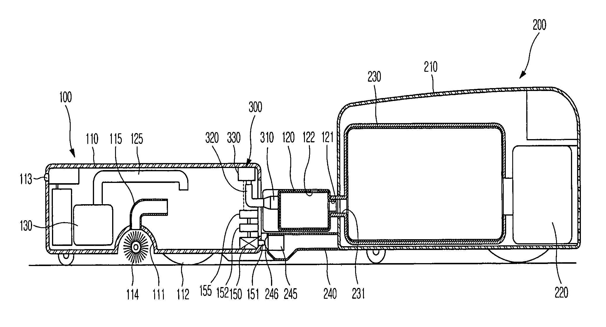
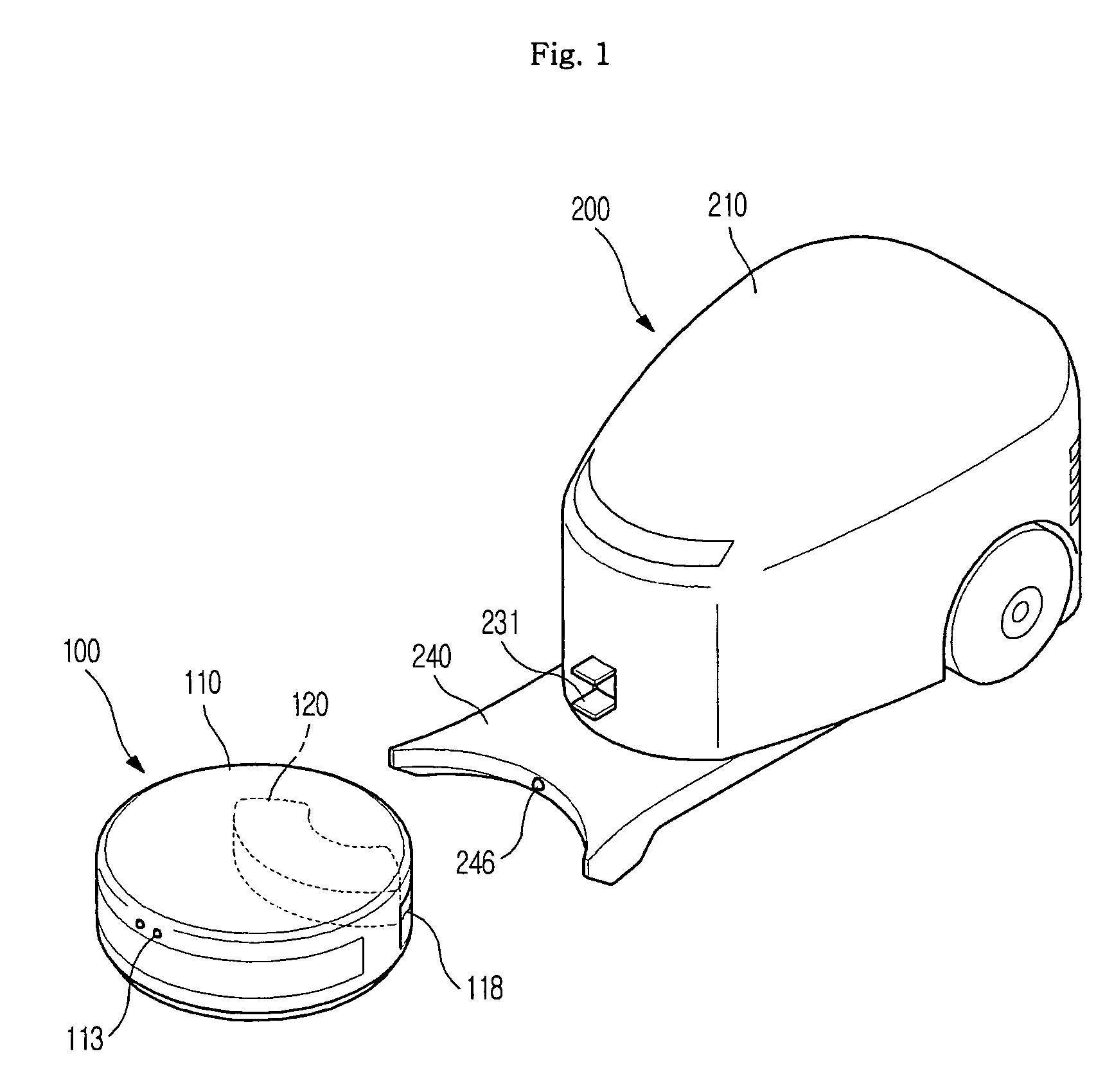
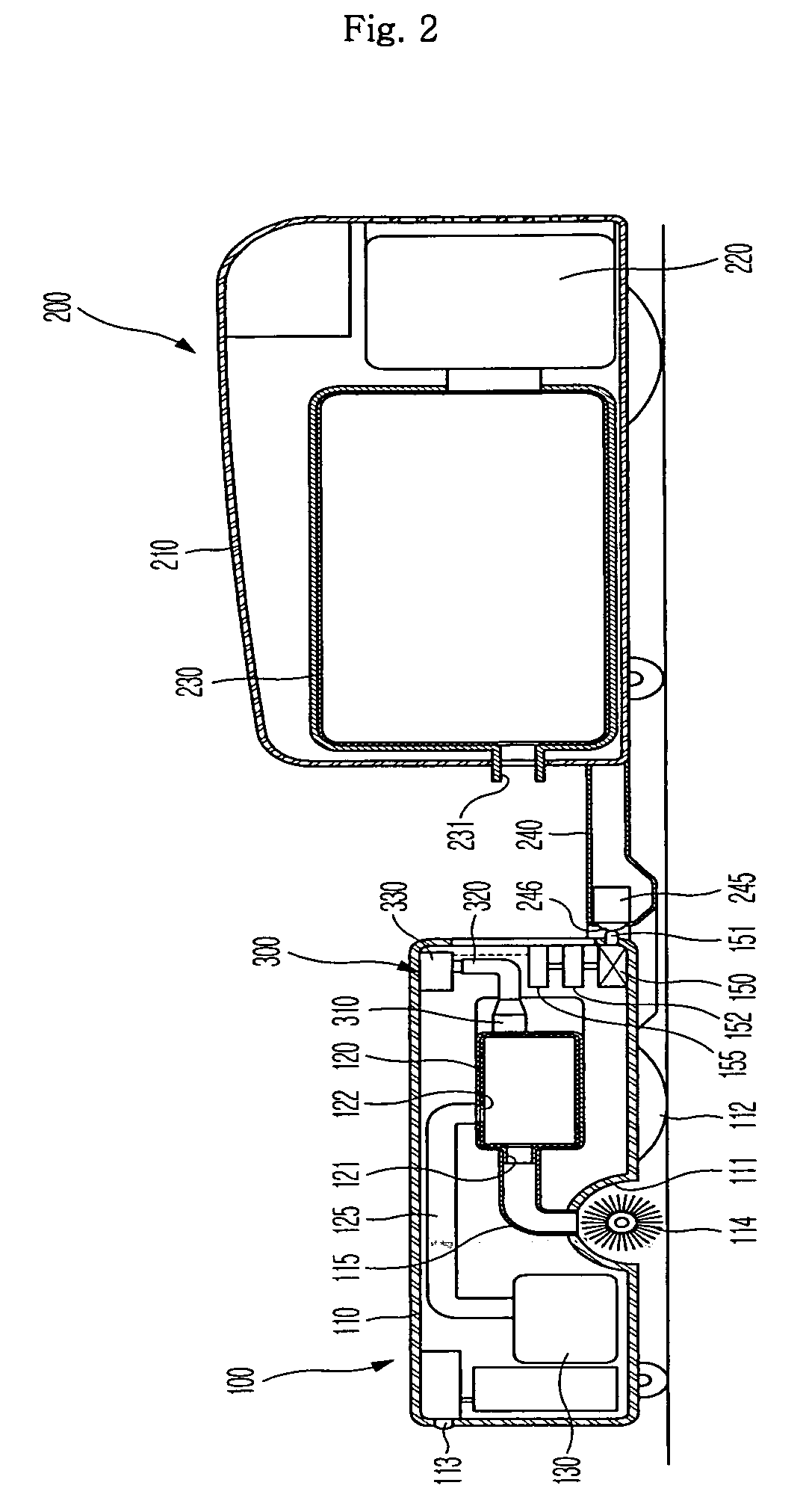
[0057]As shown in FIGS. 1 to 3, a robot cleaning system according to the present application includes a robot cleaner 100 to suction dust and a docking station 200. The robot cleaner 100 is docked when a predetermined amount of dust is collected in a first dust collector 120 mounted inside the robot cleaner 100 or when a rechargeable battery 150 needs to be charged.

[0058]The robot cleaner 100 includes a robot body 110 having a suction port 111 formed at the lower part thereof to suction dust, a first dust collector 120 mounted in the robot body 110 to collect the suctioned dust, and a first suction unit 130 communicating with the first dust collector 120 to generate a suction force necessary to suction the dust. At the suction port 111 is rotatably mounted a brush 114 to sweep the dust.

[0059]Although not shown in the drawings, the first suction unit 130 includes a motor to generate a driving force and a blowing fan receiving the driving force of the motor to generate a blowing force...

second embodiment

[0081]As shown in FIG. 5, the robot cleaning system includes a collector moving unit 300 to exchange a first dust collector 120 mounted in a robot cleaner 100 for a third dust collector 250 located on a docking station 200 so as to remove dust collected in the first dust collector 120 when the robot cleaner 100 is docked to the docking station 200.

[0082]At the upper surface of a guide member 240 is provided a location part 241, on which the third dust collector 250 is located. The third dust collector 250 has the same size and shape as the first dust collector 120. Also, the third dust collector 250 has a first port 251 and a second port 252 like the first dust collector 120. The first dust collector 120 and the third dust collector 250 are constructed in the shape of an arc constituting a portion of a circumference having a connection part 320 of the collector moving unit 300 as the center thereof.

[0083]When the third dust collector 250 is located on the docking station 200, the f...

third embodiment

[0098]As shown in FIGS. 7 and 8, the robot cleaning system includes a collector moving unit 300 to move a first dust collector 120 to a docking station 400, and move one of exchangeable dust collectors 450 loaded on the docking station 400 to a robot cleaner 100, such that the first dust collector 120 and the selected exchangeable dust collector 450 can be exchanged, so as to remove dust collected in the first dust collector 120 when the robot cleaner 100 is docked to the docking station 400.

[0099]The docking station 400 includes a loading table 410, on which a plurality of exchangeable dust collectors 450 are loaded such that the first dust collector 120 can be exchanged for one of the exchangeable dust collectors 450, and a discarding table 420, from which the first dust collector 120, which has been moved from the robot cleaner 100 to the docking station 400 by the collector moving unit 300, is discarded. At this time, the first dust collector 120 and each exchangeable dust coll...


PUM


Abstract

A robot cleaning system and a dust removing method of the same that are capable of moving a first dust collector mounted in a robot cleaner to a docking station to remove dust collected in the first dust collector. The robot cleaning system includes a robot cleaner having an opening, though which a first dust collector to collect suctioned dust is carried in and out of the robot cleaner, a docking station, to which the robot cleaner is docked to remove the dust collected in the first dust collector, and a collector moving unit to move the first dust collector to the docking station.

Description

CROSS-REFERENCE TO RELATED APPLICATIONS[0001]This application claims the benefit of Korean Patent Application No. 2006-36674, filed on Apr. 24, 2006 in the Korean Intellectual Property Office, the disclosure of which is incorporated herein by reference.BACKGROUND OF THE INVENTION[0002]1. Field of the Invention[0003]The present application relates to a robot cleaning system and a dust removing method of the same, and, more particularly, to a robot cleaning system and a dust removing method of the same that are capable of moving a first dust collector mounted in a robot cleaner to a docking station so as to remove dust collected in the first dust collector.[0004]2. Description of the Related Art[0005]A cleaner is an apparatus for cleaning a room and is typically used to remove dust. A typical example of cleaner is a vacuum cleaner that suctions foreign matter, such as dust, dirt, and loose debris, using a suction force of a suction unit.[0006]In recent years, robot cleaners have been ...

Claims


Application Information

Patent Timeline
Patent Type & Authority Patents(United States)
IPC IPC(8): A47L9/28
CPCA47L9/106A47L9/1481A47L9/1691A47L2201/024A47L9/00A47L9/10A47L9/28
Inventor HAHM, JUNG YOONKURGI, EDUARDWEE, HOONJEONG, JIN HAJOO, JAE MAN
Owner SAMSUNG ELECTRONICS CO LTD
Learn More