
Indirect bonding trays for orthodontic treatment and methods for making the same

a technology for orthodontic treatment and indirect bonding, applied in the field of indirect bonding trays for orthodontic treatment and the field of making the same, can solve the problems of unduly intruding teeth in the final position, and cannot be satisfied with the use of indirect bonding trays, and achieve the effect of improving indirect bonding trays

Active Publication Date: 2010-12-07
3M INNOVATIVE PROPERTIES CO
View PDF43 Cites 47 Cited by
  • Summary
  • Abstract
  • Description
  • Claims
  • Application Information

AI Technical Summary

Benefits of technology

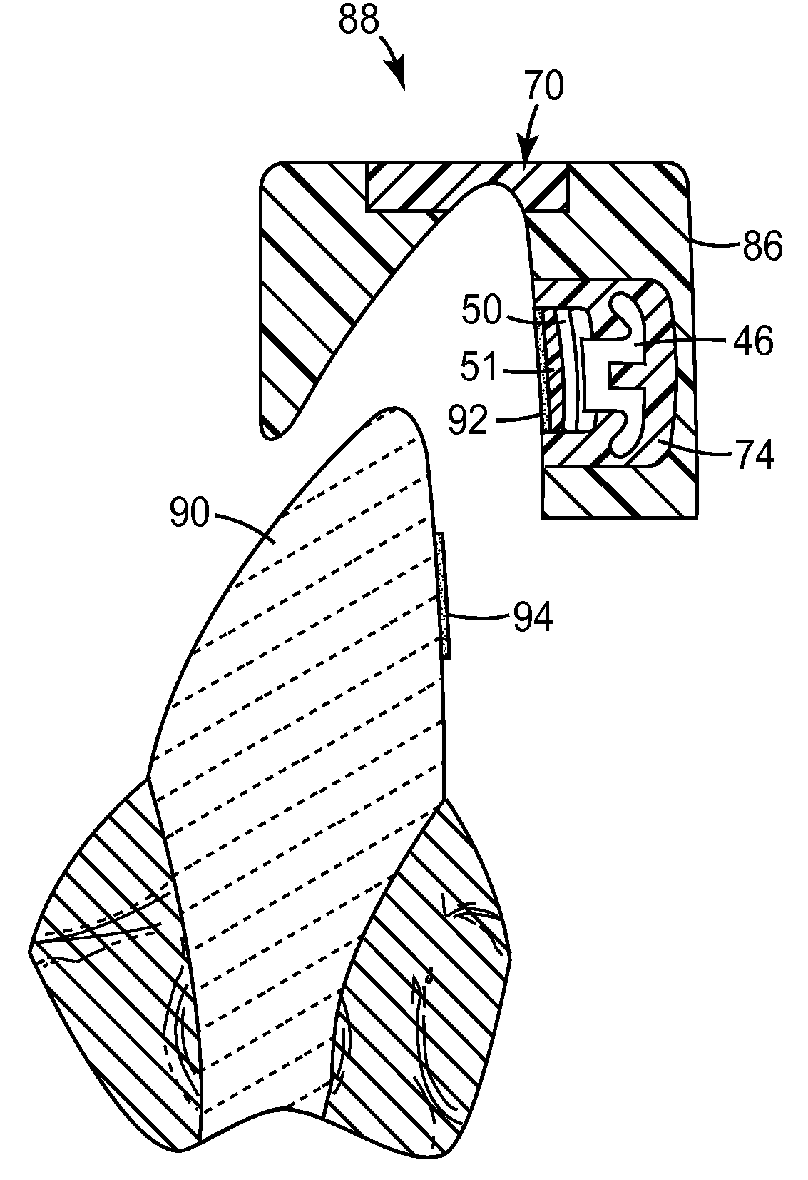
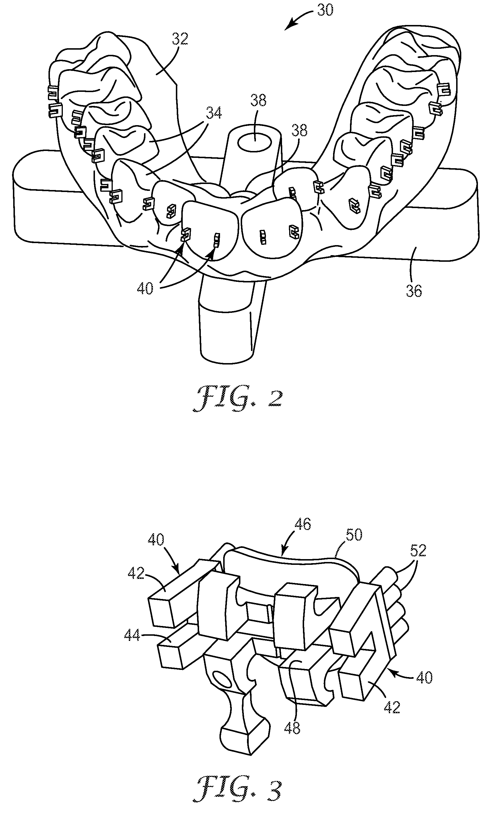
The present invention is about improving indirect bonding trays for orthodontic treatment. The invention provides a tactile snap-fit that can be easily felt when the tray is placed over the teeth, confirming that the appliances are in the desired position. The snap-fit relation of the tray to the teeth also helps to reduce unintended movement of the tray before the appliances are firmly bonded to the teeth. The invention includes a first matrix material that extends over the appliances and a second matrix material that extends over the first matrix material. The second matrix material includes a portion with a surface configuration that matches the configuration of the side tooth surfaces. The invention also includes an occlusal stop member that matches the configuration of the occlusal tooth surfaces. The invention can be made using a digital data file and rapid prototyping technology. The technical effects of the invention include improved accuracy and stability during orthodontic treatment.

Problems solved by technology

If, for example, a bracket is attached to the tooth at a location that is too close to the occlusal or outer tip of the tooth, the orthodontist using a straight-wire technique will likely find that the tooth in its final position is unduly intruded.
Some orthodontists, for example, can detect very small differences (such as, for example, 0.5 mm) in positions of appliances with the naked eye and consequently may not be satisfied with the use of indirect bonding trays that do not consistently place appliances within such tolerances.

Method used


Image

  • Indirect bonding trays for orthodontic treatment and methods for making the same
  • Indirect bonding trays for orthodontic treatment and methods for making the same
  • Indirect bonding trays for orthodontic treatment and methods for making the same

Examples


example

[0138]Experiments were conducted to compare the transfer accuracy (i.e., the accuracy of appliance placement) of the bonding trays of the present invention with bonding trays of other constructions. Three digital data files, representing the shape of three different dental arches, were obtained. Each of the three data files was used to make a bonding tray and molding vessel according to the methods described above in connection with bonding tray 88 and molding vessel 76, but using an occlusal stop member similar to the occlusal stop member 70′ illustrated in FIG. 18. To make these three trays, the first matrix material was the Emiluma brand silicone material and the second matrix material was the Memosil 2 brand vinyl polysiloxane material as mentioned above, and sufficient first matrix material was applied to the bracket appliances to generally appear as shown in FIG. 13. The occlusal stop member and tray molding vessel were made using the FullCure 720 printing material.

[0139]For p...


PUM


Abstract

An indirect bonding tray places orthodontic appliances in precise, predetermined positions on the teeth of a patient. The indirect bonding tray includes a first matrix material that extends over a set of appliances and a second matrix material that extends over the first matrix material. The indirect bonding tray also includes at least one occlusal stop member that is connected to the second matrix material for firm, relatively hard contact with the occlusal tips of the patient's teeth when the tray is received in place over the patient's dental arch.

Description

BACKGROUND OF THE INVENTION[0001]1. Field of the Invention[0002]This invention relates to trays that are used by orthodontic practitioners to bond appliances to the teeth of an orthodontic patient. The invention is also related to methods for making such bonding trays.[0003]2. Description of the Related Art[0004]Orthodontic treatment involves movement of malpositioned teeth to desired locations in the oral cavity. Orthodontic treatment can improve the patient's facial appearance, especially in instances where the teeth are noticeably crooked or where the upper and lower teeth are out of alignment with each other. Orthodontic treatment can also enhance the function of the teeth by providing better occlusion during mastication.[0005]One common type of orthodontic treatment involves the use of tiny, slotted appliances known as brackets. The brackets are fixed to the patient's teeth and an archwire is placed in the slot of each bracket. The archwire forms a track to guide movement of te...

Claims


Application Information

Patent Timeline
Patent Type & Authority Patents(United States)
IPC IPC(8): A61C3/00
CPCA61C7/146B33Y50/00B33Y80/00
Inventor KIM, SUNGHAMCORPUS, CALVIN N.LAI, MING-LAICINADER, JR., DAVID K.
Owner 3M INNOVATIVE PROPERTIES CO
Learn More