Method and system for hybrid protection in optical networks

a technology of optical network and hybrid protection, applied in the field of optical network protection of data traffic, can solve problems such as complex timing problems

Active Publication Date: 2010-11-23
ECE TELECOM LTD
View PDF14 Cites 1 Cited by
  • Summary
  • Abstract
  • Description
  • Claims
  • Application Information

AI Technical Summary

Benefits of technology

[0010]It is therefore the object of the present invention to propose a technology (a method and a system) for combined OMS and OCH protection of data traffic in telecommunication optical networks, which would allow simple selection of a correct and stable signal of the OCH protected channel in any situation in the network, and overcome a technical difficulty to distinguish signals passing via the main and the protection rings, and assist in solving a known problem of wavelength routing ambiguities (the matter relevant to the presently known combined OMS and OCH protection schemes).
[0017]The concept of rejecting the optical signal of OCH protected channel if switched by means of OMS protection to a bypass route (and thus being either unsuitable or less preferable) differs from any other method described in the prior art. The method is advantageous in that it simplifies the measures of preventing ambiguities in routing optical channels in optical networks. It can practically be performed in a number of ways, some of which will be described and illustrated later on.
[0032]By selecting the signal that has not overcome switching to an alternative route, the network avoids reaching undesirable states such as selecting a channel that originates from a wrong location. The proposed solution inherently assures that all optical channel designations reach the proper (target) receiving end. Signals that, due to a fault in the network, erroneously arrive to an OCH slot from wrong locations—will be rejected at the stage of the OCH channel selection.
[0034]The combination of the OMS and OCH protection allows protecting some specific (for example, highly important) optical channels more reliably. At the same time, presence of the OCH protection does not affect functions of the OMS protection with respect to other (non OCH protected) optical channels of the network, and vice versa.
[0035]It should be noted that in OMS protected networks, OADMs (or other optical filtering means) are customarily located only on the main contour at nodes (network elements) where traffic data is to be added to / dropped from the optical network. According to the present invention, OADMs (or the like) are located also on the protect contour, but only at the nodes being either a source node or a destination node of the OCH protected optical channels. Owing to that, the present invention proposes a low cost and scalable solution to protecting optical networks in a manner such that the network operator may select the level of protection desired for a specific channel. Namely, for low cost protection against OMS failures such as fiber cuts, OMS protection could suffice; however, for high priority signals / channels which secure protection is mandatory, individual OCH protection is offered to be used simultaneously with the OMS protection. The cost function for protection of such a multi-channel network is linear; as opposed to other protection schemes where the addition of one OCH channel requires a large amount of equipment to set-up, in the described solution the user pays an incremental amount for each OCH channel he / she wishes to add to the system.
[0036]According to another aspect of the invention, there is also provided a system capable of simultaneously performing OMS protection and OCH protection of optical traffic in a multi-channel multi-section optical communications network, the system being operative to utilize switching functions of OMS protection for simplifying implementation of the OCH protection functions, namely for simplifying selection of a suitable and stable optical signal of an OCH protected optical channel in case of a fault in at least one of the sections.

Problems solved by technology

In addition, complex timing issues are considered for adequate selection criteria.

Method used


Image

  • Method and system for hybrid protection in optical networks
  • Method and system for hybrid protection in optical networks
  • Method and system for hybrid protection in optical networks

Examples


Embodiment Construction

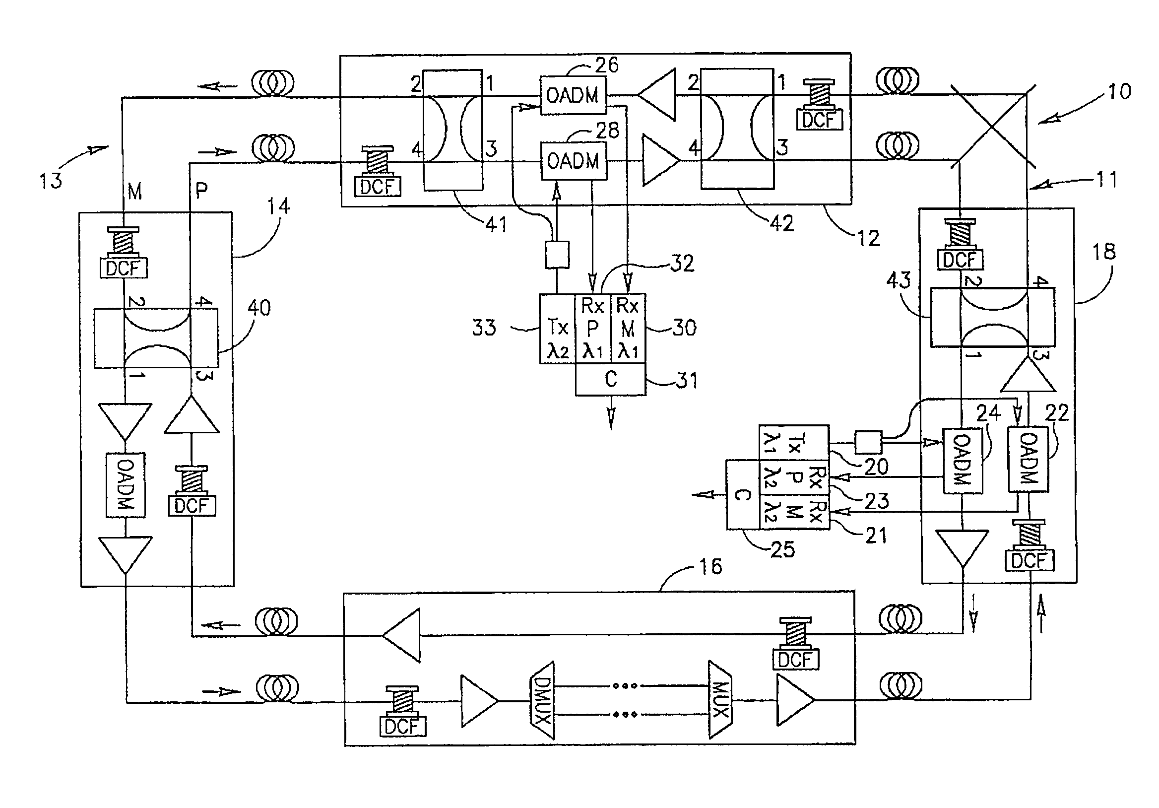
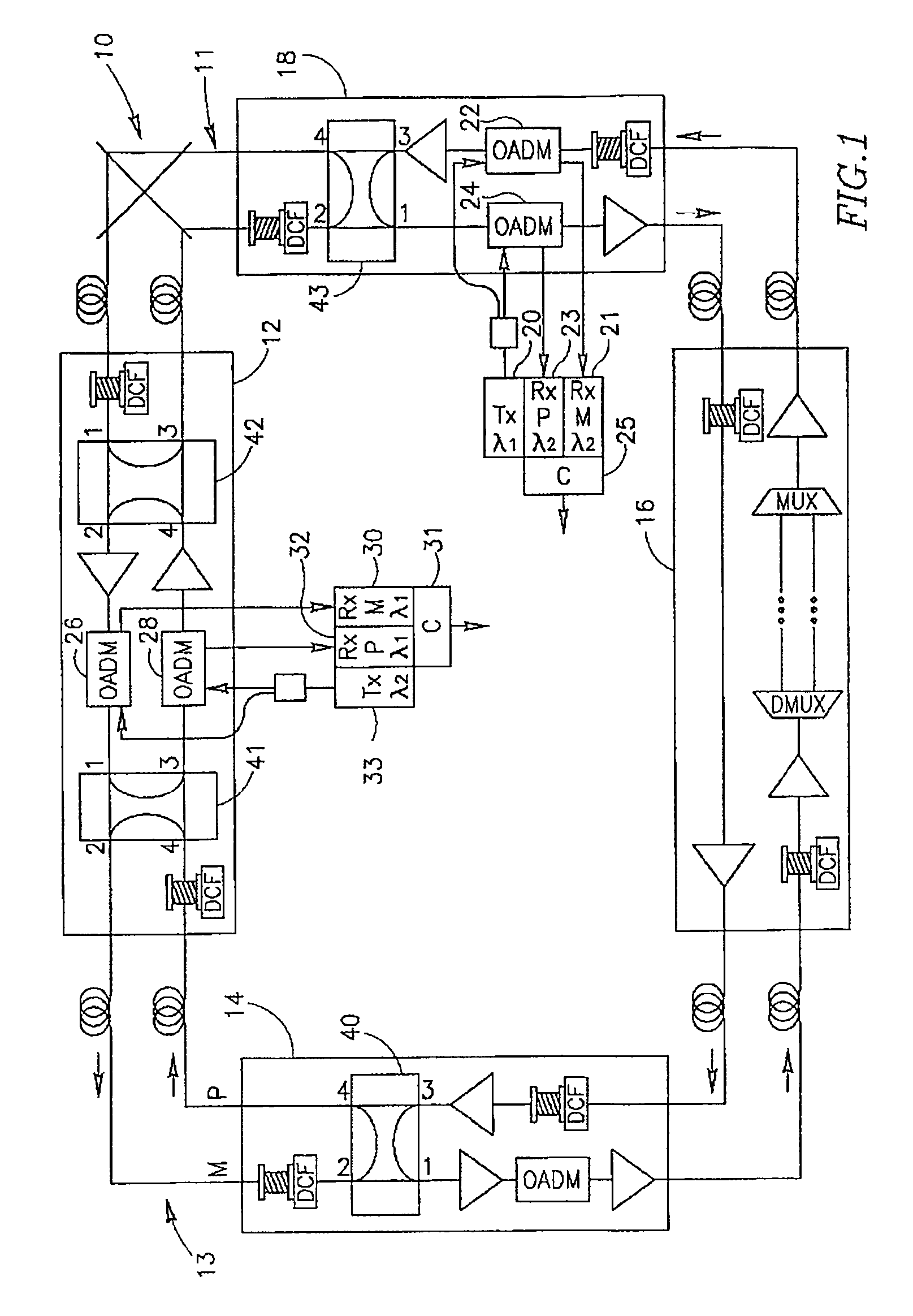
[0050]FIG. 1 illustrates an exemplary optical network, in this particular case a ring-like network 10. It comprises four network nodes 12, 14, 16 and 18 with optical amplifiers depicted as triangles, and four links formed between the nodes. Each of the links is bi-directional and comprises two segments of optical fibers for transmitting data traffic in two opposite directions. Therefore, the ring network comprises one ring formed by optical fibers transmitting data in the counterclockwise direction (let it be the outer ring called main ring and marked M) and one protect (protection) ring transmitting traffic between the nodes in the clockwise direction (the inner ring called protection ring and marked P). It should be noted that the rings' functions may change dynamically: in the course of operation the main ring may become a protection ring and vice versa. Two sections in the ring-like network (section 11 between nodes 12 and 18, and section 13 between nodes 12 and 14) are OMS prot...


PUM

PropertyMeasurementUnit
opticalaaaaaaaaaa
carrier wavelengthaaaaaaaaaa
optical signalaaaaaaaaaa

Abstract

A technique for carrying out protection of data traffic in a multi-channel multi-section optical communications network by simultaneously using Optical Multiplexed Section (OMS) protection and Optical Channel (OCH) protection; the technique comprises selection of a working optical signal in an OCH protected optical channel, in case of a fault in a section of the network, by relying on an indication associated with OMS switching functionality that is required to overcome the mentioned fault.

Description

FIELD OF THE INVENTION[0001]The invention relates to a technique for protection of data traffic in optical networks, including two types of traffic protection.BACKGROUND OF THE INVENTION[0002]Protection of traffic in optical networks can generally be classified under two types. The first type of protection, being a concept of line protection, is a so-called Optical Multiplex Section (OMS) protection used preferably in multi-channel multi-section ring networks. The ring network is formed by at least two concentric optical fiber rings capable of carrying data traffic in two opposite directions (clockwise and counterclockwise) between network elements NE in the ring. The two concentric fiber rings usually serve as a main route and a protection route for all optical channels of the network, although sometimes the main and the protection routes are arranged within the same fiber. The OMS protection ensures that in case of a fault of the traffic via a multiplex section on the main route (...

Claims


Application Information

Patent Timeline
Patent Type & Authority Patents(United States)
IPC IPC(8): G02F1/00G06F11/00G08C15/00G01R31/08H04J1/16H04J3/14H04L1/00H04L12/26H04BH04J14/02
CPCH04J14/0227H04J14/0283H04J14/0284H04J14/0291H04J14/0294H04J14/0297H04J14/0246H04J14/025
Inventor ZAACKS, MARK RAYMONDLIBMAN, AVNERMAHLAB, URI
Owner ECE TELECOM LTD
Why Eureka
Try Eureka