Eureka AIR delivers breakthrough ideas for toughest innovation challenges, trusted by R&D personnel around the world.

Drowsy state determination device and method

a technology of drowsiness and determination device, which is applied in the direction of alarms, instruments, etc., can solve the problems of erroneous determination, unable to simply differentiate between awakened and dozing, and the drowsiness level of the driver cannot be simply differentiated into two states, so as to prevent an erroneous determination of the drowsiness level

Active Publication Date: 2010-11-09
TOYOTA JIDOSHA KK
View PDF10 Cites 11 Cited by
  • Summary
  • Abstract
  • Description
  • Claims
  • Application Information

AI Technical Summary

Benefits of technology

[0008]The present invention provides a drowsy state determination device and method that can prevent an erroneous determination of the drowsiness level of the driver by determining the drowsiness level of the driver based on a first threshold for differentiating eye closures that occur during a fixed period and that last for a prescribed period or more, and a second threshold for differentiating the occurrence frequency of the eye closures that last for the period indicated by the first threshold or more.
[0012]The controller may decrease the first threshold stored in the storage device according to a traveling speed of the vehicle.
[0013]The controller may decrease the first threshold stored in the storage device according to the duration of a continuous traveling time of the vehicle.
[0017]The present invention can provide a drowsy state determination device and method that can prevent an erroneous determination of the drowsiness level of the driver.

Problems solved by technology

The drowsiness level of the driver, however, cannot be simply differentiated into two states, namely awakened and dozing.
Therefore, the doze detector may erroneously determine that the driver is dozing, even in the case where the driver is actually awakened, once the driver closes his / her eyes for a period indicated by the threshold or more, even if the threshold for comparison with the accumulated duration is set optimally.
Such an erroneous determination can be made when, for example, the driver is so dazzled by a bright light in the surroundings, such as a backlight, that he / she narrows or closes his / her eyes.
In addition, since the drowsiness level of the driver is simply differentiated into two levels, namely awakened and dozing, the doze detector may erroneously determine that the driver is simply dozing, even in the case where the driver is actually feeling slight drowsiness or heavy drowsiness.
That is, the above doze detector has a problem of erroneously determining the drowsiness level of the driver.

Method used


Image

  • Drowsy state determination device and method
  • Drowsy state determination device and method
  • Drowsy state determination device and method

Examples


first embodiment

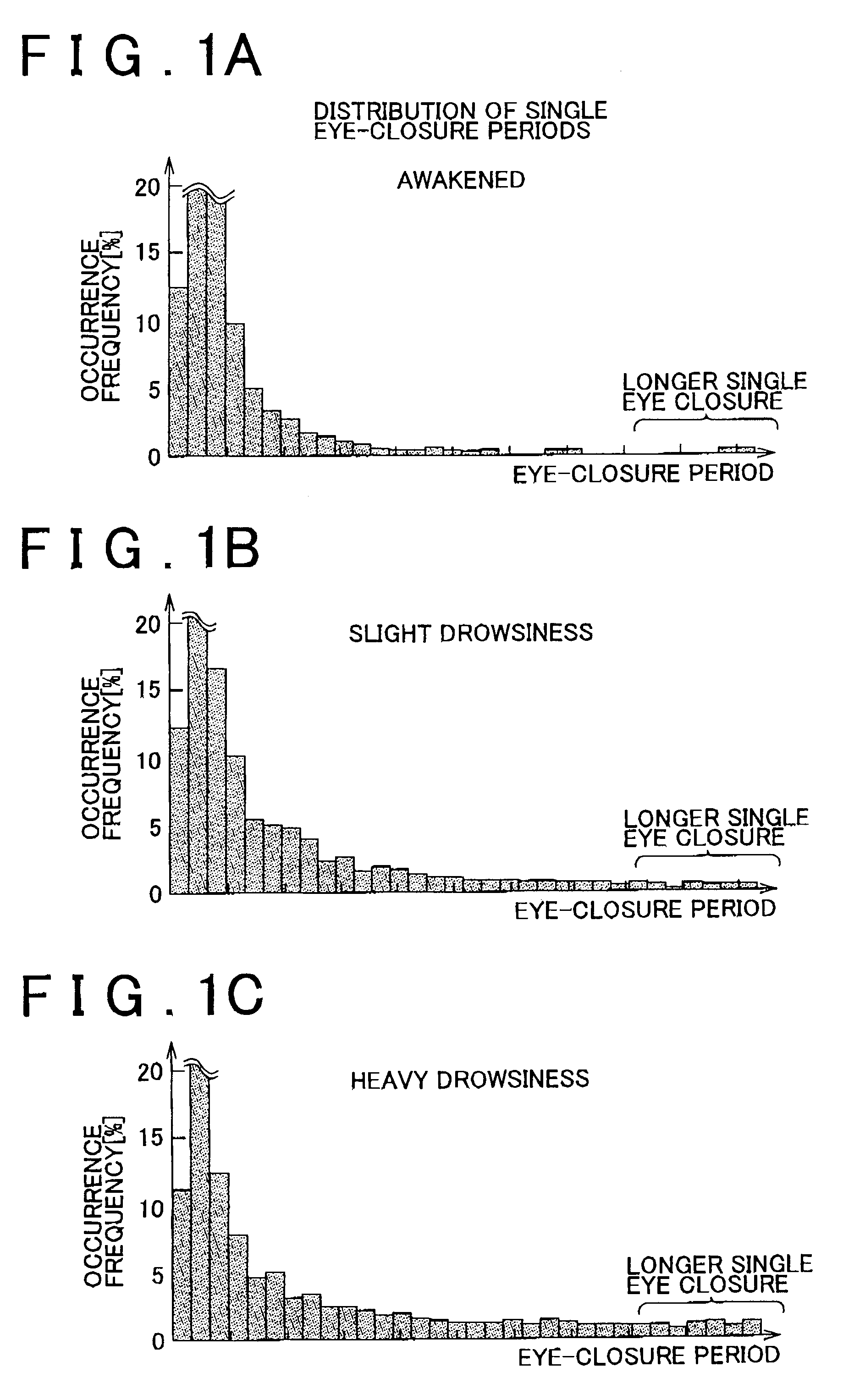
[0023]FIGS. 1A to 1C are histograms representing the distribution of a plurality of durationpecific eye closures of the driver that occur during a prescribed time for respective drowsiness levels of the driver. In the histograms of FIGS. 1A to 1C, the horizontal axis represents the duration of respective eye closures (hereinafter each eye closure is referred to as “single eye closure”), and the vertical axis represents the occurrence frequency of single eye closures of each duration. The histogram of FIG. 1A represents the case where the driver is awakened. The histogram of FIG. 1B represents the case where the driver is feeling slight drowsiness. The histogram of FIG. 1C represents the case where the driver is feeling heavy drowsiness. In this embodiment, the “drowsiness level” is higher (heavier) as the driver is drowsier. In the description of this embodiment, the drowsiness level of the driver is determined from three levels, namely awakened, slightly drowsy, and heavily drowsy,...


PUM


Abstract

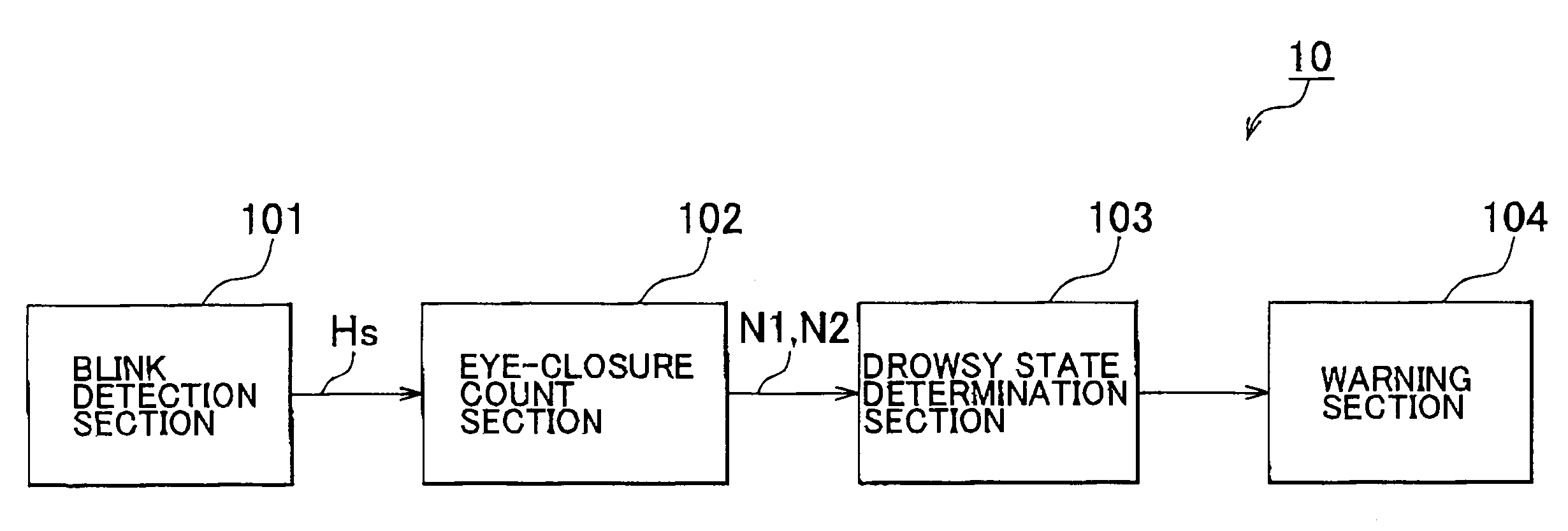
A blink detection section generates an eye-closure signal indicating the duration of a period for which the driver closes his / her eyes. An eye-closure count section calculates the respective occurrence frequencies of single eye closures in a prescribed measurement period for a first eye-closure period threshold and a second eye-closure period threshold, based on the eye-closure signal and the respective eye-closure period thresholds. A drowsy state determination section compares the respective occurrence frequencies with the first eye-closure frequency threshold and the second eye-closure frequency threshold to determine which of the drowsiness levels corresponding to the respective thresholds the drowsiness level of the driver is at.

Description

INCORPORATION BY REFERENCE[0001]The disclosure of Japanese Patent Application No. 2007-194834 filed on Jul. 26, 2007, including the specification, drawings and abstract is incorporated herein by reference in its entirety.BACKGROUND OF THE INVENTION[0002]1. Field of Invention[0003]The present invention relates to a drowsy state determination device and method, and more specifically to a device and method that determines the drowsiness level of the driver of a mobile unit such as an automobile.[0004]2. Description of Related Art[0005]In recent years, there have been proposed devices that determine the drowsiness level of the driver of a mobile unit such as an automobile (see Japanese Patent Application Publication No. 6-219181 (JP-A-6-219181), for example). The doze detector disclosed in JP-A-6-219181 accumulates the duration of blinks (hereinafter referred to as “eye closures”) of the driver of a prescribed time or more over a fixed period. The doze detector determines that the drive...

Claims


Application Information

Patent Timeline
Patent Type & Authority Patents(United States)
IPC IPC(8): G08B23/00
CPCG08B21/06
Inventor NAKAGOSHI, AKIRAKIMURA, KENJIOKOMBI-DIBA, BERTIN RODOLPHE
Owner TOYOTA JIDOSHA KK
Why Eureka
Eureka Blog
Learn More