
Long-range cattle identification system

a cattle identification and long-range technology, applied in the field of long-range cattle identification systems, can solve the problems of time-consuming and stressful cattle activities, producers are generally limited to reading electronic identification and rfid devices

Inactive Publication Date: 2010-11-09
THE BOARD OF RGT UNIV OF OKLAHOMA
View PDF33 Cites 28 Cited by
  • Summary
  • Abstract
  • Description
  • Claims
  • Application Information

AI Technical Summary

Benefits of technology

"The present invention is a long-range animal identification system that uses electronic information tags to track and track individual animals. The system includes a plurality of electronic information tags attached to each animal, communication devices that communicate with the electronic information tags, and a backend database. The electronic information tags are designed to transmit and receive information with each other, creating a mesh network that allows information to relay from tag to tag, resulting in an effective range of several hundred meters for each tag. The system is efficient, cost-effective, and can be used to track and track animals in real-time, reducing stress and improving efficiency for veterinary practices and producers."

Problems solved by technology

This activity is time consuming and stressful to the cattle.
For this reason, producers are generally limited to reading the electronic identification of each animal when scheduled vaccinations or other veterinary practices are required of the entire herd.
Another limitation of the passive RFID devices is that they require inductive, close proximity electromagnetic radiation for power.
The wands and panels that supply this inductive power are typically very expensive.

Method used


Image

  • Long-range cattle identification system
  • Long-range cattle identification system
  • Long-range cattle identification system

Examples


Embodiment Construction

[0014]Presently preferred embodiments of the invention are shown in the above identified figures and described in detail below. In describing the preferred embodiments, like or identical reference numerals are used to identify common or similar elements. The figures are not necessarily to scale and certain features in certain views of the figures may be shown exaggerated in scale the interest of clarity and conciseness.

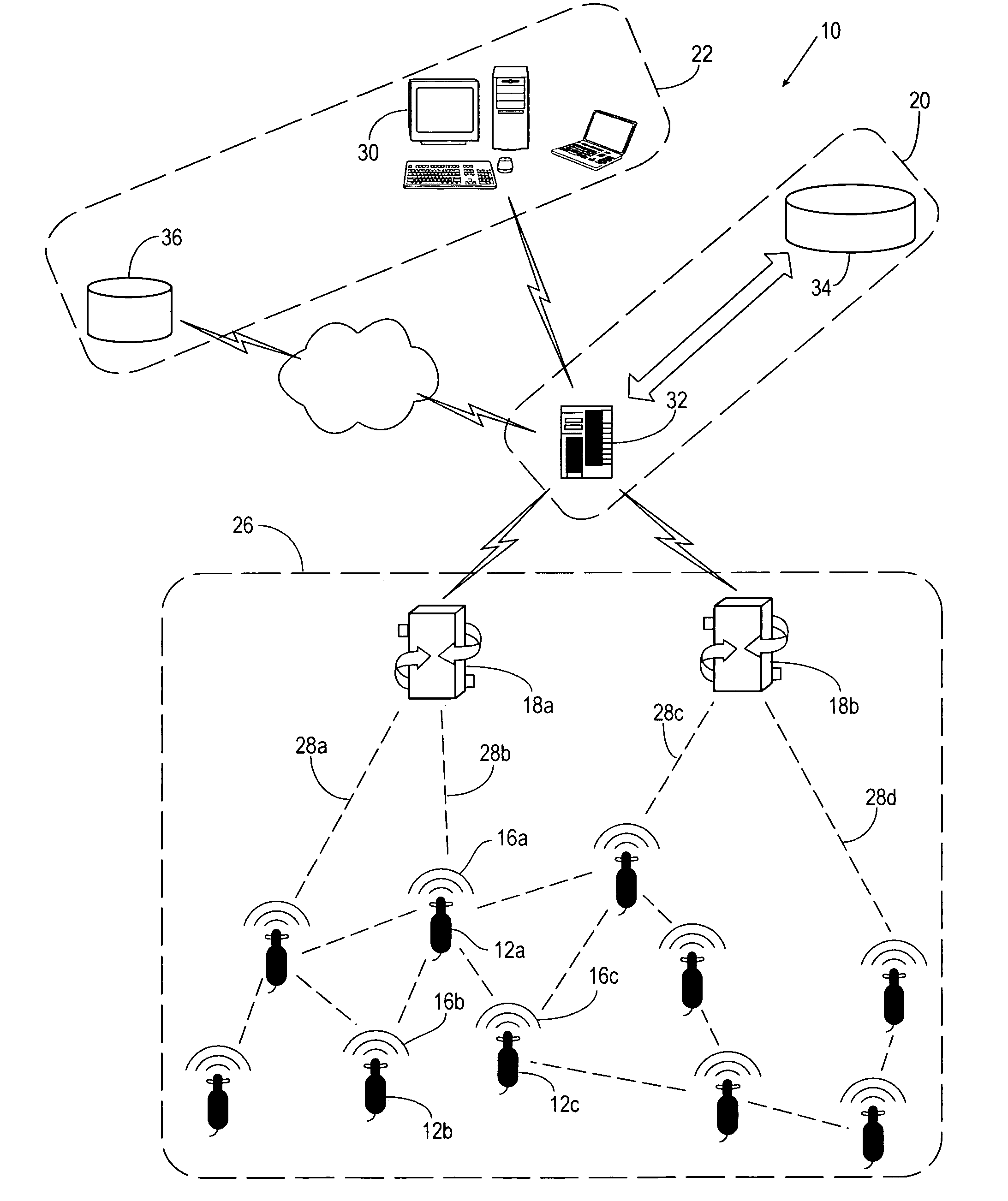
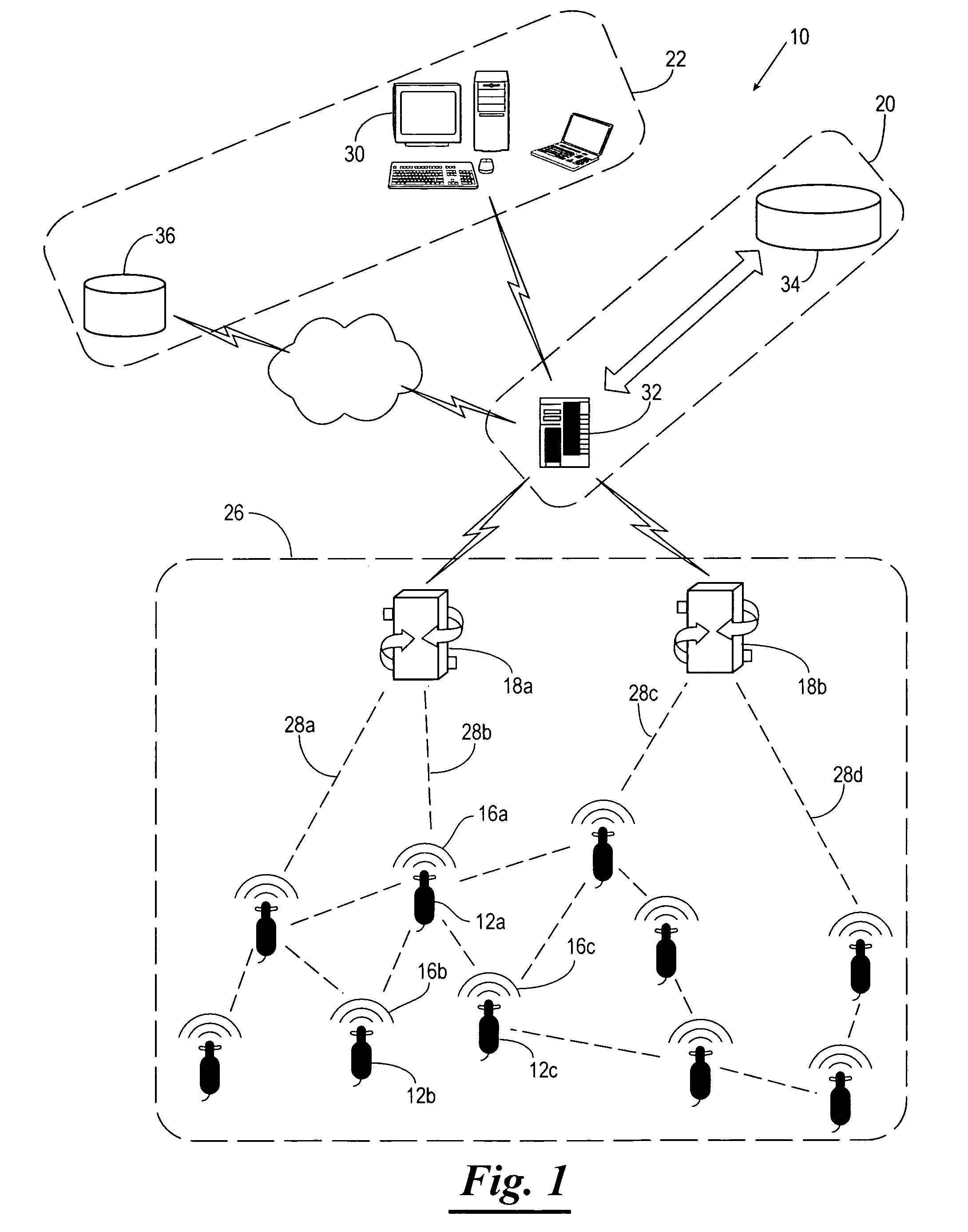
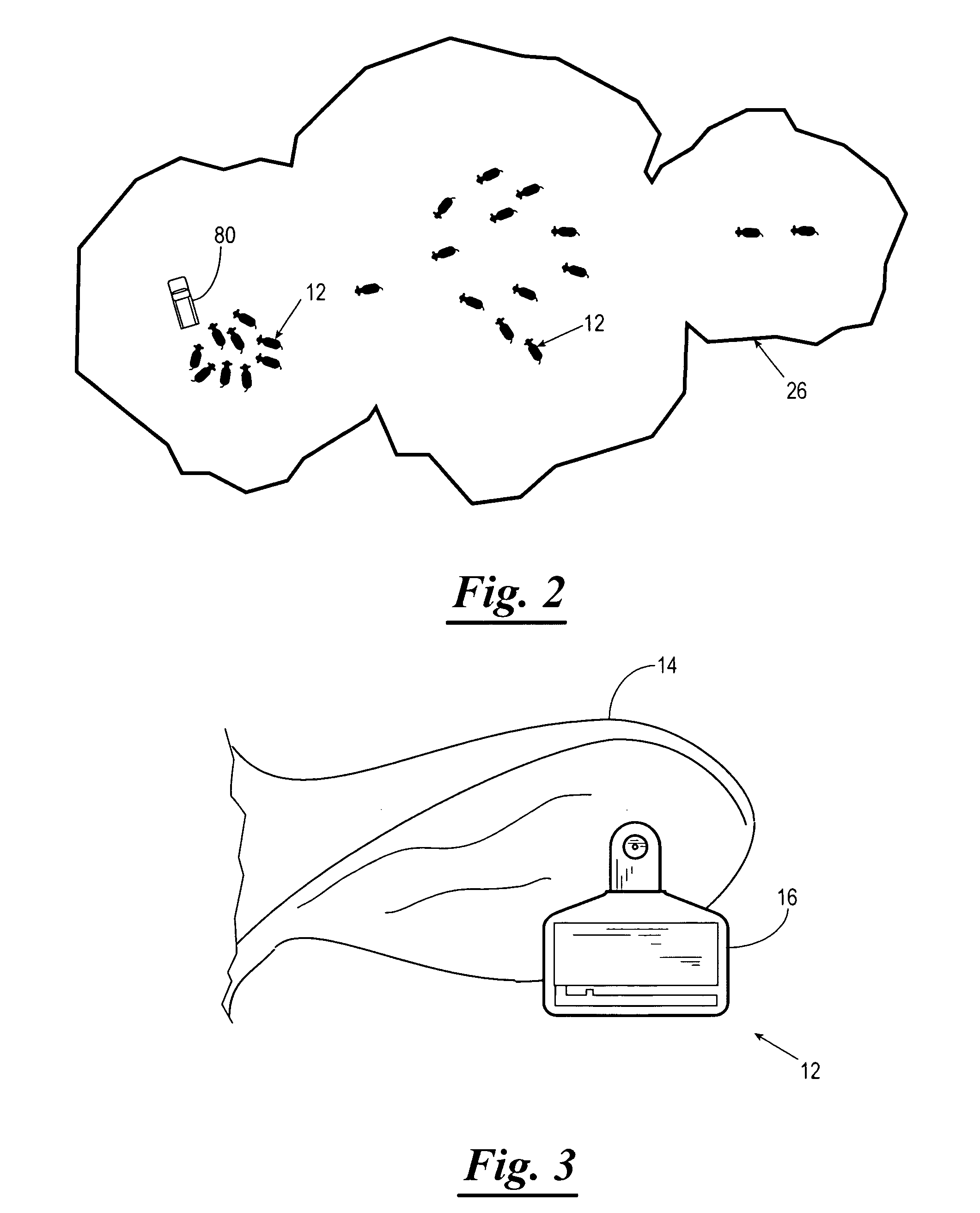
[0015]Referring now to the drawings, and in particular to FIG. 1, shown therein and designated by reference numeral 10 is a long-range animal identification system constructed in accordance with the present invention. For purposes of clarity, the long-range animal identification system 10 will be referred to hereinafter as the “system 10”. The system 10 serves to monitor a plurality of animals 12, only three of the animals 12 being labeled in FIG. 1 by reference numerals 12a, 12b, and 12c for purposes of clarity. The animals 12 can be livestock or wild animals. Exampl...


PUM


Abstract

A long-range cattle identification system used to monitor a plurality of animals. The system uses a plurality of electronic information tags that are attachable to animals. The electronic information tags transmit and receive electronic information with at least one other electronic information tag. The electronic information tags are spatially disposed so that one electronic information tag can transmit and receive at least one other electronic information tag's individual electronic information to form a mesh network. The system includes a communication device that can communicate with at least one electronic information tag and receive information from that tag. The communication device can also receive the information contained in all the other electronic information tags in the mesh network through the at least one electronic information tag.

Description

CROSS-REFERENCE TO RELATED APPLICATIONS[0001]The present patent application claims priority to the provisional patent application identified by U.S. Ser. No. 60 / 673,962 filed on Apr. 22, 2005; as well as the provisional patent application identified by U.S. Ser. No. 60 / 720,360 filed on Sep. 23, 2005. The entire content of both of the afore mentioned provisional patent applications is hereby incorporated herein by reference.STATEMENT REGARDING FEDERALLY SPONSORED RESEARCH AND DEVELOPMENT[0002]Not applicable.BACKGROUND OF THE INVENTION[0003]Existing electronic identification methods of cattle rely on traditional radio frequency identification (RFID) devices. With these devices, a wand must be passed nearby (typically within one meter) each animal's ear tag. The short reading range of the existing RFID devices mandated corralling and trapping individual animals. In order to accomplish this, the rancher traps each animal one by one in a working chute. This activity is time consuming and...

Claims


Application Information

Patent Timeline
Patent Type & Authority Patents(United States)
IPC IPC(8): G08B13/14G08B23/00G08B1/08A61B5/00
CPCA01K11/006A01K29/00G06K7/0008G06K2017/0045G06K2017/0051
Inventor HASSELL, JOHN W.
Owner THE BOARD OF RGT UNIV OF OKLAHOMA
Learn More