
Heat dissipation device for a display projector lamp module

Inactive Publication Date: 2010-11-09
HON HAI PRECISION IND CO LTD
View PDF4 Cites 1 Cited by
  • Summary
  • Abstract
  • Description
  • Claims
  • Application Information

AI Technical Summary

Problems solved by technology

It is generally known that the high-intensity light source implemented in known image display projectors typically generates a large amounts of heat.
Furthermore, the display projector is used in a high heat state for a long time and the life time of the display projector is consequently shortened.
Thus, heat generated by the light sources is accumulated in the cover near the outlets, and a temperature of the outlets is higher than other portions of the cover; thus, increasing the risks of injury (such as being scaled) when handling or accidentally touching the image display projector.

Method used


Image

  • Heat dissipation device for a display projector lamp module
  • Heat dissipation device for a display projector lamp module
  • Heat dissipation device for a display projector lamp module

Examples


Embodiment Construction

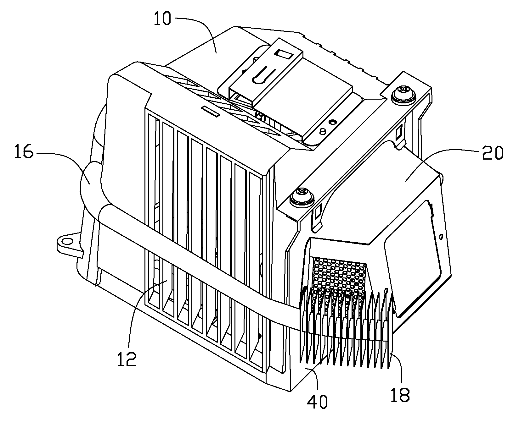
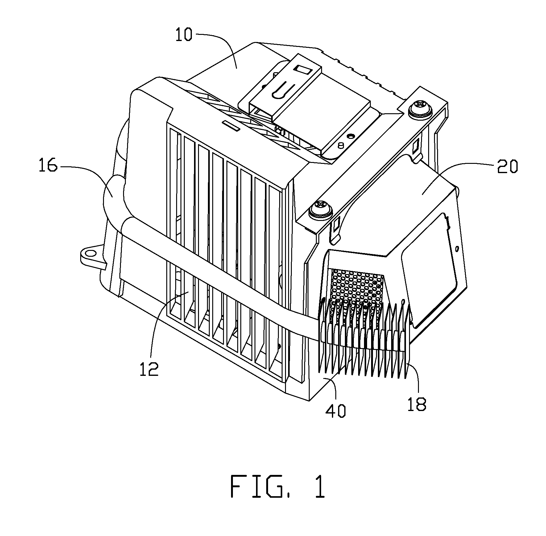
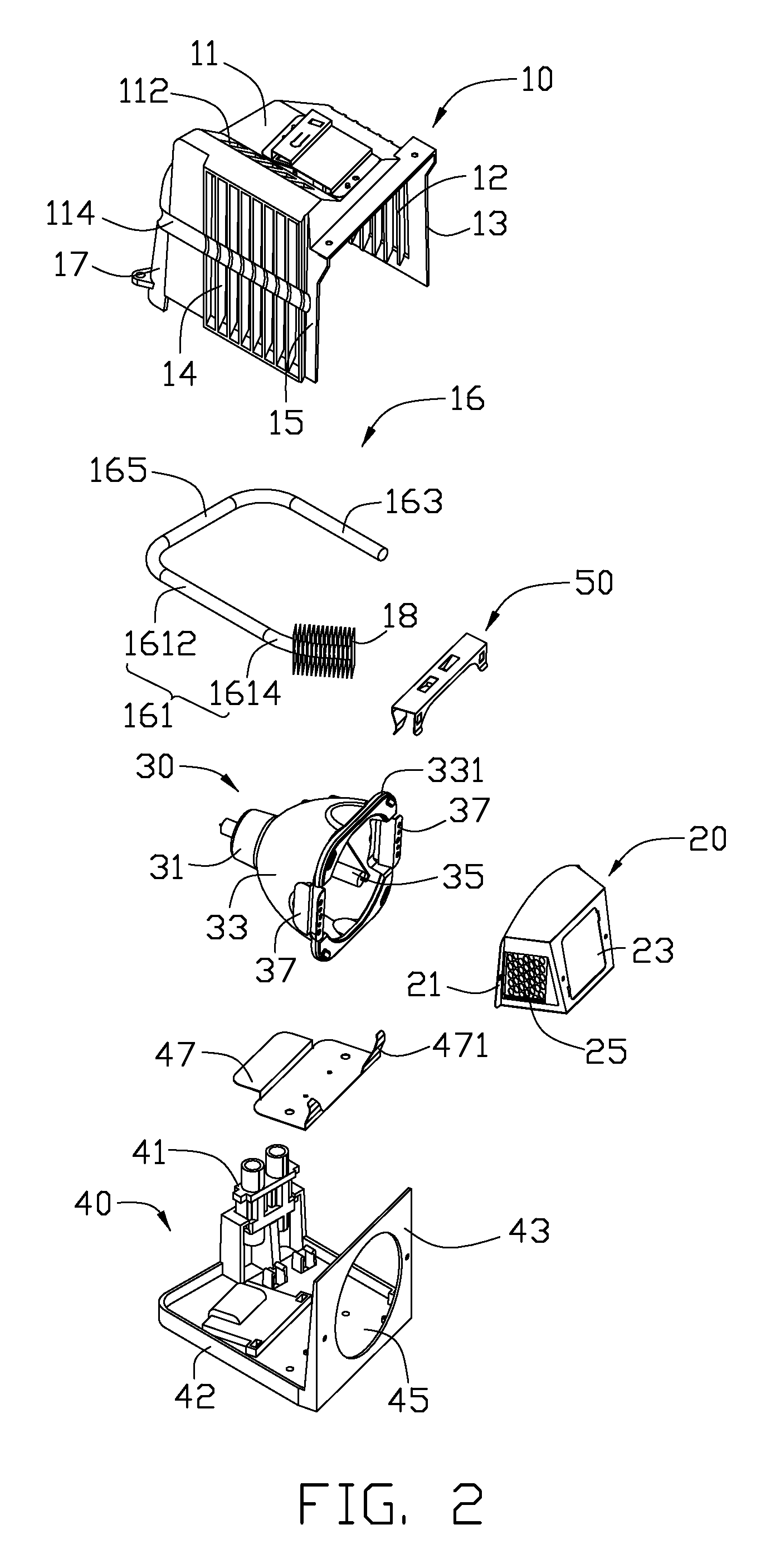
[0014]Referring to FIGS. 1-2, a display projector lamp module mounted in a display projector (not shown) in accordance with the present embodiment of the present invention includes a lamp 30, a metal lampshade 20 corresponding to the lamp 30, a mounting member 40 supporting the lamp 30 and a metal cover 10 cooperating with the mounting member 40 for housing the lamp 30 therein. A heat dissipation device is attached to the display projector lamp module. The heat dissipation device comprises a plurality of first fins 12 and second fins 14 formed on lateral sidewalls of the cover 10 respectively, and a heat pipe 16 mounted a peripheral of the cover 10 and thermally contacting the first and second fins 12, 14. A plurality of third fins 18 is mounted on a distal end of the heat pipe 16 near to the cover 20. The display projector defines a plurality of inlets (not shown) and outlets (not shown) opposing the inlets.

[0015]The mounting member 40 comprises a rectangular base 42, a driving cir...


PUM


Abstract

A display projector lamp module includes a lamp, a mounting member supporting the lamp, a metal cover and a heat pipe. The mounting member and the metal cover cooperates to defines a room, and the lamp is received in the room. A plurality of first and second fins is mounted on opposite sidewalls of the cover to dissipate heat generated by the lamp. The heat pipe is mounted around a periphery of the cover and thermally contacts with the first and second fins.

Description

BACKGROUND OF THE INVENTION[0001]1. Field of the Invention[0002]The present invention relates to a display projector lamp module, and particularly to a display projector lamp module having heat dissipation device to improve heat dissipation efficiency thereof.[0003]2. Description of Related Art[0004]Image display projectors generate display images and project them to display screens for viewing by one or more viewers. The display images are formed and projected by passing light from a high-intensity light source such as a plurality of high intensity lamps through an image-forming medium such as a translucent film or liquid crystal display. Alternatively, the display images are formed through digital light processing which uses digital micromirror devices to form the display images. It is generally known that the high-intensity light source implemented in known image display projectors typically generates a large amounts of heat. In addition, as the high-intensities, e.g., 2000 or mo...

Claims


Application Information

Patent Timeline
IPC IPC(8): G03B21/16
CPCG03B21/16G03B21/20
Inventor SUN, MING-CHIH
Owner HON HAI PRECISION IND CO LTD
Learn More