
Expansion-sealed flood control gate

a flood control gate and expansion seal technology, applied in the field of barriers, can solve the problems of increasing the risk, uneven compression stress distribution across the compression strip, and suffering of people, and achieve the effect of higher geometric toleran

Inactive Publication Date: 2010-10-19
DUNG CHEN YUAN
View PDF7 Cites 29 Cited by
  • Summary
  • Abstract
  • Description
  • Claims
  • Application Information

AI Technical Summary

Benefits of technology

[0008]A main objective of the present invention is to provide an expansion-sealed flood control gate which has the characteristics of active filling and uniform packing stresses that have higher geometric tolerances, even if the slits between the water board, the constraint tracks and the ground emerge under unexpected geometrical changes. Encased expandable sealing tubes balloon to mend the slits.
[0009]Another objective of the present invention is to provide an expansion-sealed flood control gate, which reinforces the entire structural strength to increase back support against water pressure and provide a double seal to prevent leakage.
[0010]Another objective the present invention is to provide an expansion-sealed flood control gate, which requires only screws, pins etc. for positioning; therefore, there are no worries concerning uneven compression forces and the assembly or maintenance is both easy and convenient.

Problems solved by technology

Due to global warming effects, and as the global climate gradually changes, more flooding is occurring all over the world, and people are suffering from these natural disasters.
The typical flood control gate usually utilizes a water barrier overlaying method to deal with different flood heights and employs a heavy water barrier; as a result, the gap between each water barrier increases with the number of water barriers, which also increases the risk.
In order to achieve ease of construction and lower construction costs, the traditional flood control gate design still utilizes right angled equipment for the corners; however, sharp bends in the compression strip causes uneven compression stress distributions across the compression strip.
In addition, the junction of the compression strip at the corners are made by physical contact, therefore, the compression stresses at the conjunction are not completely not predictable or controllable, which is the basis of the most common leakage problems in traditional flood control gates.
However, increasing the number of compression force application points causes an increased compression frequency, which results in longer construction times and higher material costs.
Furthermore, increased compression forces causes compression stress concentration effects on local materials to be more severe at the compression force application points, which causes material fatigue and potential points of failure.
In addition, the longer the width of the flood control gate the more difficult it is for mechanical processes or construction applications to keep the gap constant or the gap to a minimum between the compression strip and the gate lip.
Higher process accuracies lead to much higher equipment costs, and an increased strip thickness for gap adjustment purposes causes higher strip material costs.
Another issue is, if the gate lip is accidently damaged and deformed during construction or later operations, the reliability of the damaged area becomes unpredictable.
Therefore, based on either common experience or theoretical analysis, the more gaps generated in the construction of the flood control gate, the higher the associated risk.
Therefore, both performance and maintenance issues for a stacked flood control gate are very worrying.

Method used


Image

  • Expansion-sealed flood control gate
  • Expansion-sealed flood control gate
  • Expansion-sealed flood control gate

Examples


Embodiment Construction

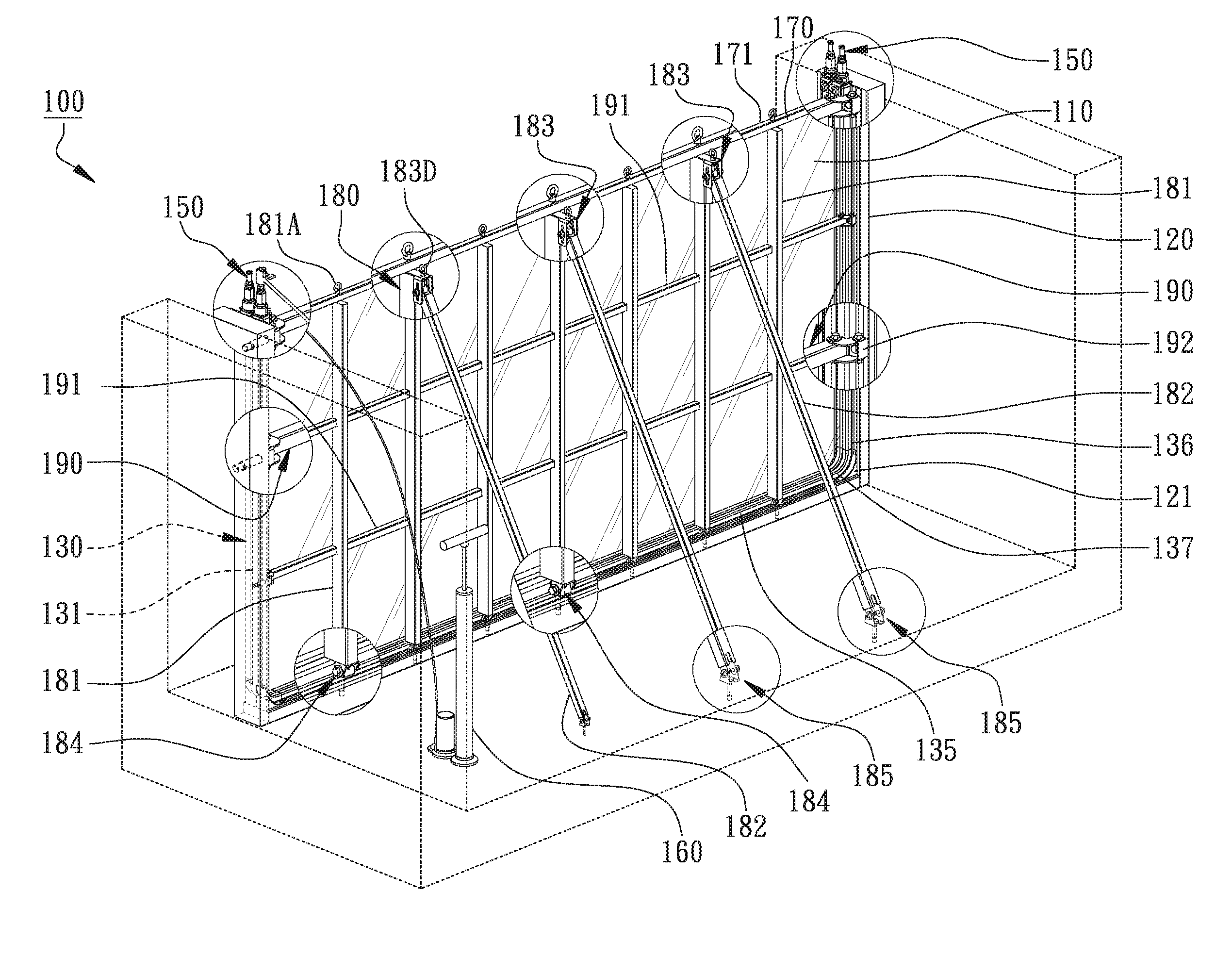
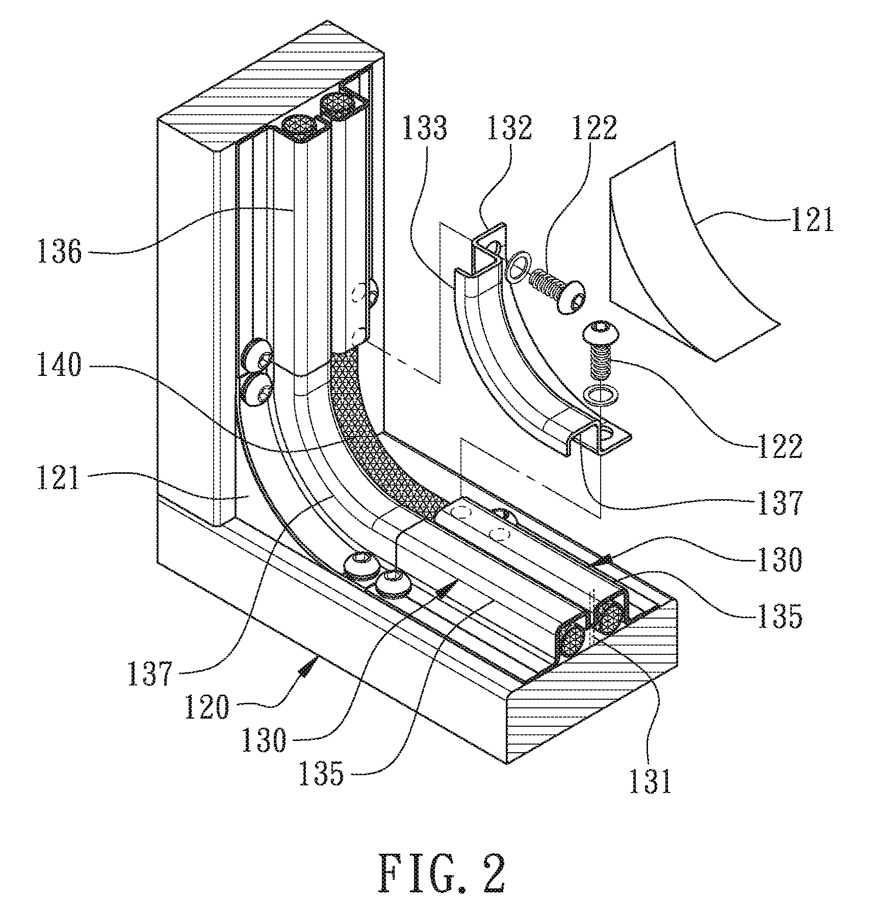
[0051]Please refer to FIG. 1 and FIG. 2. FIG. 1 is a perspective view of an expansion-sealed flood control gate according to an embodiment of the present invention. FIG. 2 is a detailed view of a constraint track and a corner track of the expansion-sealed flood control gate according to the embodiment of the present invention. An expansion-sealed flood control gate 100 comprises a water barrier 110, a frame structure 120, at least two constraint tracks 130, at least one encased expandable sealing tube 140 and a plurality of adapters 150. The water barrier 110 has direct contact with the water and is made of a light weight and high strength material which is easy to store and assemble. Preferably, the water barrier 110 is a transparent material to permit viewing of the water level. The water barrier 110 may be made of PC boards, which can be rolled up for storage, and so may require much less storage space while providing strength and which will not be affected by surface damage. As ...


PUM


Abstract

Disclosed is an expansion-sealed flood control gate, comprising a water board, a frame structure, two symmetrical constraint tracks, at least one encased expandable sealing tube, and a plurality of adapters. A U-shaped slot is formed between the two symmetrical constraint tracks for plugging in the water board. Each constraint track has a U-shaped expanding compression chamber connecting from one end to the other end to accommodate the tube inside. The adapters are connected with the open ends of the tube and fixed on the constraint tracks at the connected ends. Accordingly, there can be effectively repelled floods that the tube with the characteristics of active filling and uniform packing stress have the higher geometric tolerance, even if the slits between the water board, the constraint tracks and ground emerge the unexpected geometrical change, the encased expandable sealing tubes are ballooned to mend the slits.

Description

BACKGROUND OF THE INVENTION[0001]1. Field of the Invention[0002]The present invention relates to a barrier structure, and, more particularly, to an expansion-sealed flood control gate.[0003]2. Description of the Related Art[0004]Due to global warming effects, and as the global climate gradually changes, more flooding is occurring all over the world, and people are suffering from these natural disasters. In order to prevent flooding in buildings, people often use flood control gates at the entrance of the building. The typical flood control gate usually utilizes a water barrier overlaying method to deal with different flood heights and employs a heavy water barrier; as a result, the gap between each water barrier increases with the number of water barriers, which also increases the risk. In order to achieve ease of construction and lower construction costs, the traditional flood control gate design still utilizes right angled equipment for the corners; however, sharp bends in the com...

Claims


Application Information

Patent Timeline
Patent Type & Authority Patents(United States)
IPC IPC(8): E02B7/00
CPCE02B3/102E02B7/54
Inventor DUNG, CHEN-YUAN
Owner DUNG CHEN YUAN
Learn More