
Electronically commutated external rotor motor with a circuit board

a technology of circuit board and external rotor motor, which is applied in the direction of circuit electrostatic discharge protection, overvoltage circuit protection, mechanical energy handling, etc., can solve the problems of motor damage and electrostatic discharg

Active Publication Date: 2010-10-12
EBM PAPST ST GEORGEN & -
View PDF6 Cites 38 Cited by
  • Summary
  • Abstract
  • Description
  • Claims
  • Application Information

AI Technical Summary

Benefits of technology

The present invention provides a motor with a circuit board that has two apertures: one near the Hall magnetic sensor for detecting motor position, and another at a remote position from the sensor. The circuit board has electrical conductors that lead to a grounding element, which acts as a "lightning rod" to protect the motor from damage or destruction due to electro-static discharge (ESDs). The technical effect of this invention is to provide a simple and effective way to protect motors from ESDs.

Problems solved by technology

In circuit boards of this kind, the problem arises that Electro-Static Discharges (ESDs) can occur during operation; these sparks or discharges can cause damage to the motor, particularly to digital electronic components used to direct motor operations.

Method used


Image

  • Electronically commutated external rotor motor with a circuit board
  • Electronically commutated external rotor motor with a circuit board
  • Electronically commutated external rotor motor with a circuit board

Examples


Embodiment Construction

[0015]FIG. 1 is a longitudinal section through a fan 20 having an electronically commutated external-rotor motor 21 and a circuit board 46 according to an embodiment of the present invention. Fan 20 is depicted at greatly enlarged scale, by way of example, as a radial fan. It could alternatively, for example, be an axial fan or a diagonal fan. In a practical embodiment of the fan such as the one shown in FIG. 1, the height is approximately 15 mm and the width approximately 51 mm, i.e. FIG. 1 depicts this fan enlarged approximately 4.5 times. Other fan types in other sizes can, of course, likewise be equipped with correspondingly modified circuit boards.

[0016]Motor 21 has an external rotor 22, an internal stator 50 having a stator lamination stack 50′, and a bearing tube 70 mounted on a plastic part 80. With this design, bearing tube 70, as well as an external rotor 22 journaled in it, are insulated by the plastic part. The rotor is separated from internal stator 50 by an air gap, an...


PUM


Abstract

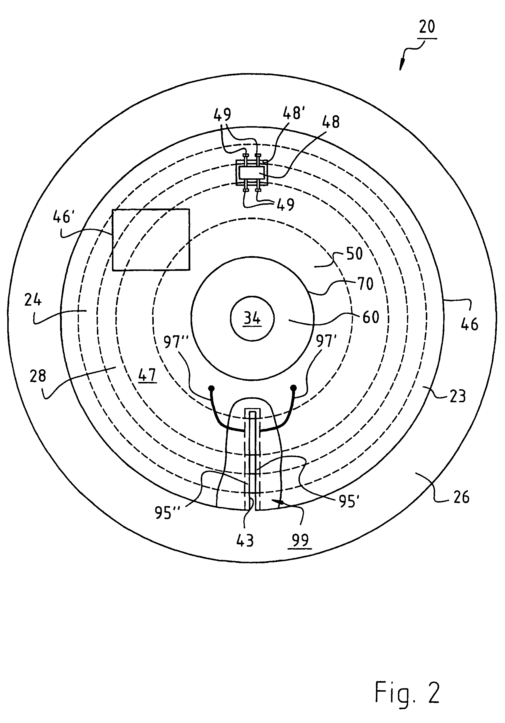
An electronically commutated motor (ECM 21) has reduced vulnerability to Electro-Static Discharge (ESD). The motor has an internal stator (50) and an external rotor (22) equipped with a permanent magnet (28), which rotor is separated by an air gap from the internal stator (50). The rotor has a shaft (34) on which a magnetic yoke element (24) is mounted. A leakage flux region on an end face (27) of the magnet (28) actuates a Hall sensor (48) located adjacent a first aperture (48′) in a circuit board (46) supporting electronic control components. In order to prevent static discharges from passing through the first aperture (48′) and endangering the electronic components, the circuit board (46) is formed with a second aperture (43) on whose edge is provided at least one electrical conductor (95′, 95″), connected to ground (112), to which any charge that builds up during operation can harmlessly discharge.

Description

FIELD OF THE INVENTION[0001]The present invention relates to an electronically commutated external-rotor motor having a circuit board.BACKGROUND[0002]In such electronically commutated motors (ECMs), a circuit board is used to support electronic components for controlling the motor. A so-called “window,” i.e. a hole, is provided in this circuit board, and a Hall sensor is arranged adjacent the window, in order to generate rotor position signals. This allows the motor to be compactly designed, since no additional space is needed for the Hall sensor.[0003]In circuit boards of this kind, the problem arises that Electro-Static Discharges (ESDs) can occur during operation; these sparks or discharges can cause damage to the motor, particularly to digital electronic components used to direct motor operations.[0004]It is therefore an object of the present invention to provide a novel electronically commutated external-rotor motor having substantially reduced vulnerability to such ESD events....

Claims


Application Information

Patent Timeline
Patent Type & Authority Patents(United States)
IPC IPC(8): H02K29/08
CPCH02K11/0089H02K29/08H05K1/0259H02K1/2786H02K2211/03H05K2201/09063H02K11/40H02K1/2791
Inventor COSCO, PINOFISCHER, KLAUS S.
Owner EBM PAPST ST GEORGEN & -
Learn More