
Control of fluid conditions in bulk fluid distribution systems

a technology of fluid pressure and bulk fluid, which is applied in the direction of process and machine control, liquid handling, instruments, etc., can solve the problems of semiconductor wafer defects, spiked particle concentration, and complex process of semiconductor device manufactur

Inactive Publication Date: 2010-10-12
AIR LIQUIDE ELECTRONICS US LP
View PDF28 Cites 16 Cited by
  • Summary
  • Abstract
  • Description
  • Claims
  • Application Information

AI Technical Summary

Benefits of technology

"The patent describes a method and apparatus for controlling the pressure of a fluid in a bulk fluid distribution system. The method involves alternately dispensing fluid from two vessels to a point of use while keeping the pressure of the fluid constant. The apparatus includes sensors, regulators, and a controller that receives a control signal from a sensor and adjusts the pressure of the fluid in each vessel based on the sensor signal and a change in head pressure. The technical effect of this invention is to provide a more stable and consistent fluid pressure in the distribution system, which improves the efficiency and reliability of the system."

Problems solved by technology

The manufacture of semiconductor devices is a complex process that often requires over 200 process steps.
However, an abrupt change in the flow rate of the fluid through the filters causes hydraulic shock to the filters which results in a release of previously filtered particles into the fluid thereby causing a spike in the particle concentration.
Accordingly, pressure and flow fluctuations of the fluid can result in fluctuations of the particle concentration in the fluid, which may lead to defects in the semiconductor wafers.
As will be discussed further below, typical fluid distribution systems having vacuum-pressure engines cause pressure fluctuations in the supply line which may adversely affect the flow and purity conditions of the fluid supplied to the tools.
A problem with the system of FIG. 1a is that it does not maintain a stable pressure of the fluid in the supply line 123. FIG. 1b shows a simplified illustration of how the pressure of the fluid in supply line 123 fluctuates over time.
In addition, another problem with system 200 is that it continually adjusts the pneumatic signal to the slave regulator of the non-dispensing or standby vessel.
Thus, the slave regulator for the non-dispensing vessel incurs significant wear and tear on the slave regulator of the standby vessel.

Method used


Image

  • Control of fluid conditions in bulk fluid distribution systems
  • Control of fluid conditions in bulk fluid distribution systems
  • Control of fluid conditions in bulk fluid distribution systems

Examples


example 1

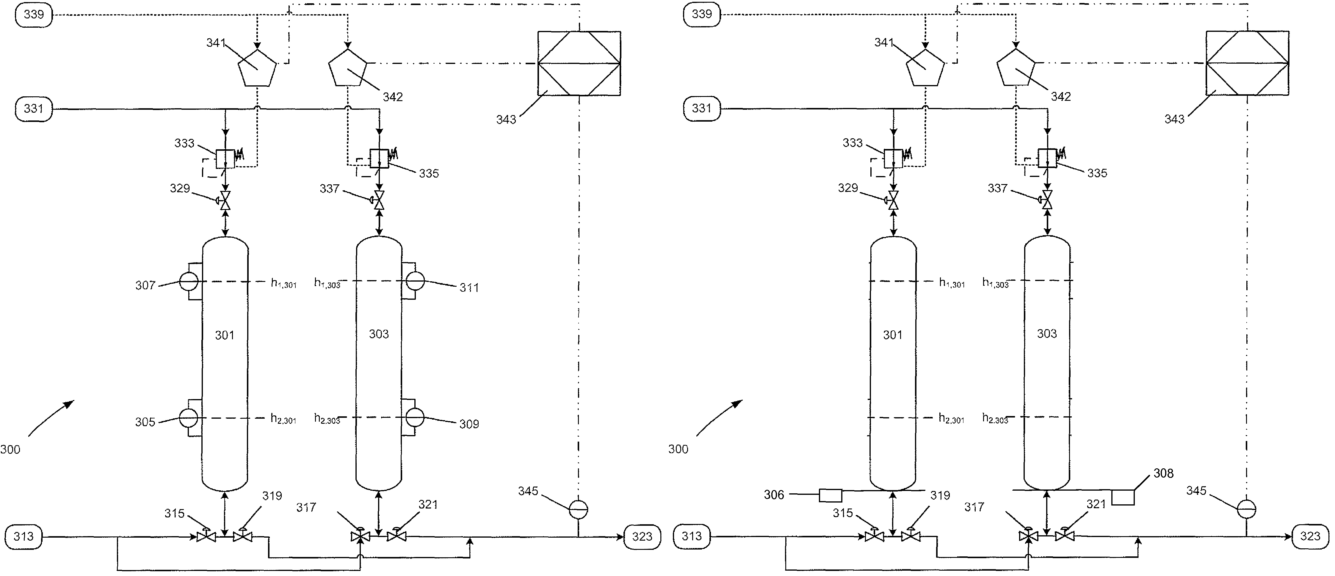
[0036]Assume Vessel 301 has completed a fill cycle by filling the vessel with fluid to its high level (307 as shown in FIG. 3a) and is standing by while vessel 303 completes its dispense cycle by dispensing fluid to its low level (309 as shown in FIG. 3a).

[0037]During the dispense cycle of vessel 303, the controller 343 is periodically or continuously receiving a signal from sensor 345 and adjusting the inert gas pressure supplied to vessel 303 to maintain a predetermined flow condition (e.g. pressure, flow rate or the like) in the supply line 323. As vessel 303 dispenses from its high level (311 as shown in FIG. 3a) to its low level (309 as shown in FIG. 3a) the head pressure of the fluid decreases between level h1,303 and level h2,303 in accordance with the following equation for the change in head pressure of a fluid in a vessel: ΔP303=P1,303−P2,303=pg(h1,303−h2,303) (where p=density of the fluid and g=9.8 m / s2).

[0038]Consequently, to prevent a decrease in the pressure of the flu...


PUM


Abstract

An improved bulk fluid distribution for supplying process fluids to semiconductor process tools. The improved system having an alternating pressure vessel engine substantially eliminates pressure fluctuations in the bulk fluid supply line due to head losses from the changing weight of the fluid in the dispensing vessels. The system also enables flexible control of the flow conditions of the fluid in the fluid supply line.

Description

FIELD OF THE INVENTION[0001]The present invention relates to an apparatus and method for controlling the pressure of a fluid in a bulk fluid distribution system. More particularly, the present invention provides improved apparatus and methods for controlling pressure of semiconductor process fluids (e.g. ultra-high purity or slurry fluids) in a bulk fluid supply line that supplies process tools used in semiconductor manufacturing or other related applications.BACKGROUND OF THE INVENTION[0002]The manufacture of semiconductor devices is a complex process that often requires over 200 process steps. Each step requires an optimal set of conditions to produce a high yield of semiconductor devices. Many of these process steps require the use of fluids to, inter alia, etch, expose, coat, and polish the surfaces of the devices during manufacturing. In high purity fluid applications, the fluids must be substantially free of particulate and metal contaminants in order to prevent defects in the...

Claims


Application Information

Patent Timeline
Patent Type & Authority Patents(United States)
IPC IPC(8): G05D11/00B67D7/02B67D7/08B67D7/72
CPCB67D7/0272F04F1/02Y10T137/3127Y10T137/2569Y10T137/27B67D7/08B67D7/72
Inventor GERKEN, DAVID
Owner AIR LIQUIDE ELECTRONICS US LP
Learn More