
Pilot signal transmission method and mobile communication system

a mobile communication system and signal transmission technology, applied in multiplex communication, orthogonal multiplex, wireless commuication services, etc., can solve the problems of inability to accurately perform interpolation/extrapolation, and inability to accurately perform extrapolation/extrapolation. , to achieve the effect of accurate channel estimation

Inactive Publication Date: 2010-10-05
FUJITSU LTD
View PDF5 Cites 30 Cited by
  • Summary
  • Abstract
  • Description
  • Claims
  • Application Information

AI Technical Summary

Benefits of technology

The present invention provides a pilot signal transmission method and a mobile communication system that overcome the limitations and disadvantages of the related art. The method and system enable accurate channel estimation and efficient pilot signal transmission. The technical effects include improved pilot signal compensation and data signal transmission, as well as reduced interference and improved signal quality.

Problems solved by technology

However, since channel distortion occurs in a very complicated manner, it is difficult to accurately perform interpolation / extrapolation when channel distortion is high.
Also, in urban areas, normally, channel distortion is greater and more complicated in the frequency direction than in the time direction, and an extrapolation method provides less accurate results than an interpolation method.
This, in turn, greatly reduces the accuracy of channel estimation and thereby degrades the reception characteristics of a data signal.
On the other hand, making the bandwidth of a pilot signal larger than that of a data signal may cause interference between pilot signals of different users.

Method used


Image

  • Pilot signal transmission method and mobile communication system
  • Pilot signal transmission method and mobile communication system
  • Pilot signal transmission method and mobile communication system

Examples


first embodiment

1. First Embodiment

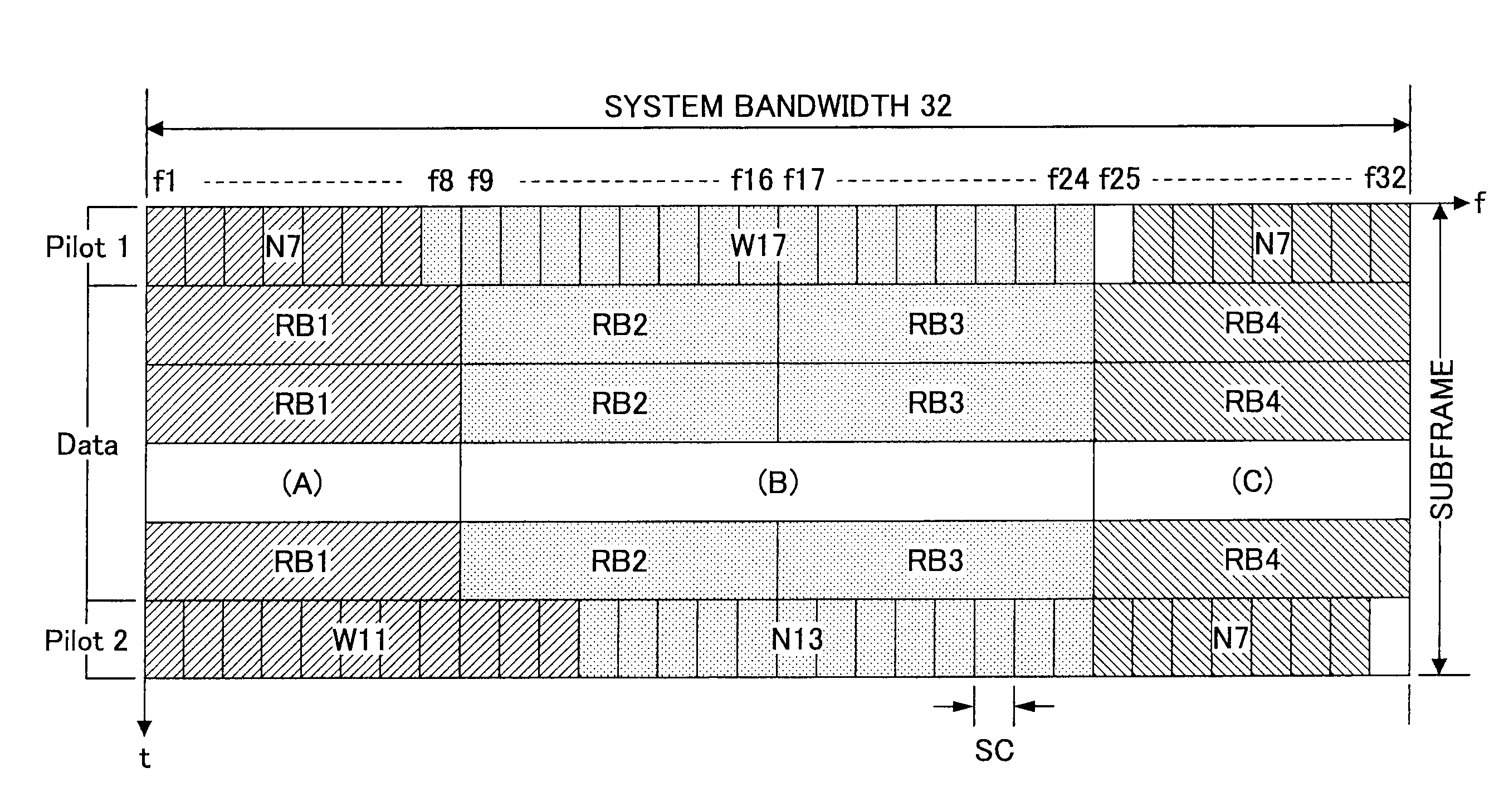
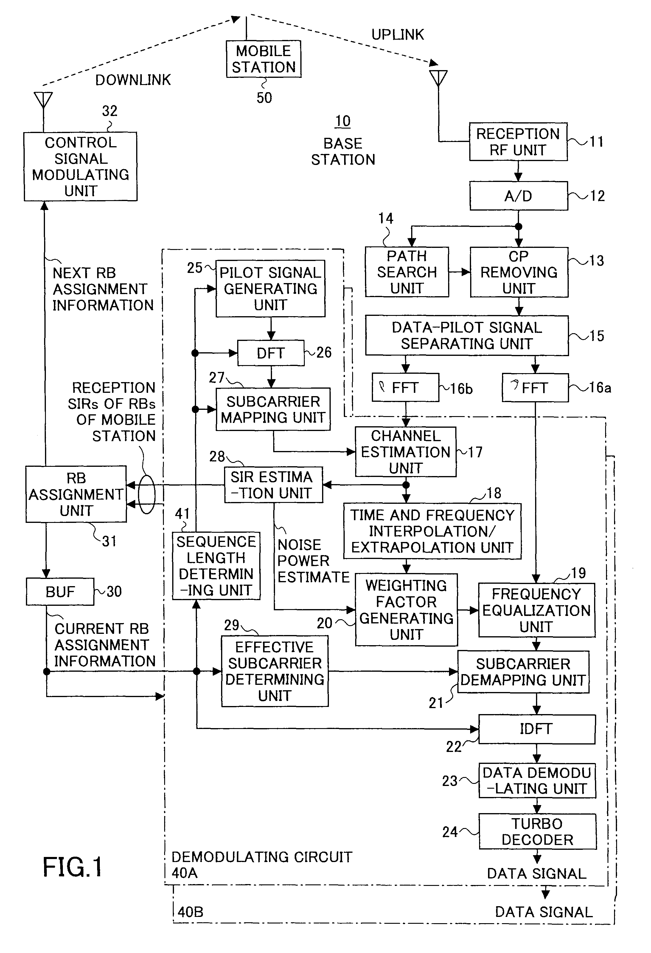
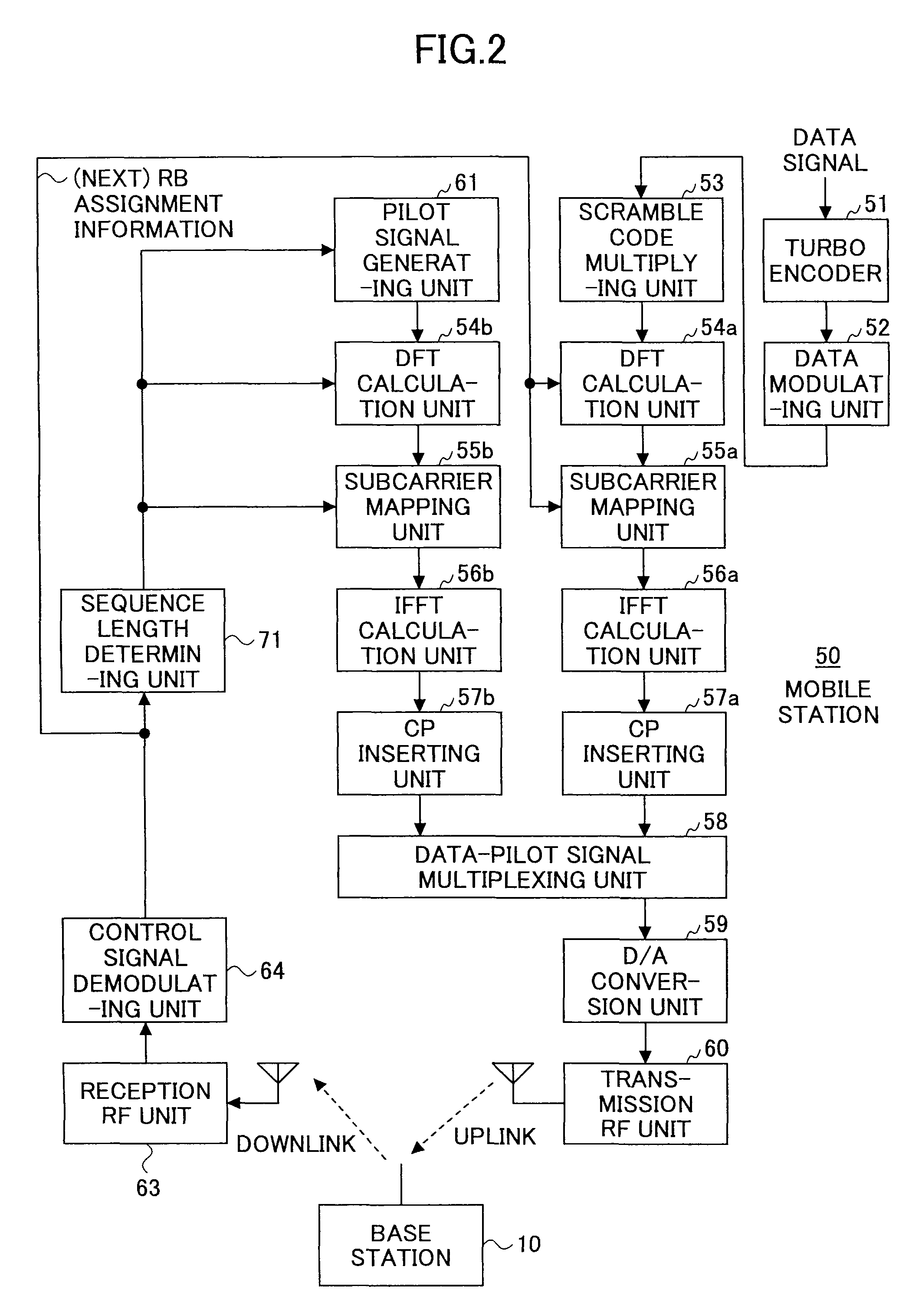
[0040]Preferred embodiments of the present invention are described below with reference to the accompanying drawings. In the drawings, the same reference numbers are used for the same or corresponding parts. FIG. 1 and FIG. 2 are drawings illustrating an exemplary mobile communication system based on DFT-spread-OFDM according to a first embodiment of the present invention.

[0041]FIG. 1 is a block diagram illustrating an exemplary configuration of an exemplary receiving unit of a base station 10. An uplink radio signal from a mobile station 50 is quadrature-demodulated by a reception RF unit 11 and thereby converted into a baseband signal, and the baseband signal is converted from analog to digital by an A / D converting unit 12. A path search unit 14 performs a correlation calculation in the time domain between the A / D converted signal (received signal) and a replica of a transmitted pilot signal and thereby detects a reception timing (starting point of an effective ...


PUM


Abstract

A method of transmitting pilot signals for channel compensation in a mobile communication system based on DFT-spread-OFDM is disclosed. In the disclosed method, a first pilot signal and a second pilot signal are time-division multiplexed together with a data signal of a user into a time-division multiplexed signal which data signal is assigned a certain bandwidth; the time-division multiplexed signal is frequency-division multiplexed together with time-division multiplexed signals of other users when wirelessly transmitted; and the first pilot signal is assigned a bandwidth larger than the bandwidth of the data signal and the second pilot signal is assigned a bandwidth smaller than the bandwidth of the data signal.

Description

BACKGROUND OF THE INVENTION[0001]1. Field of the Invention[0002]The present invention generally relates to a pilot signal transmission method and a mobile communication system, and more particularly relates to a pilot signal transmission method and a mobile communication system where a pilot signal for channel compensation is time-division multiplexed together with a data signal of a user, which data signal is assigned a certain bandwidth and to be wirelessly transmitted based on DFT-spread-OFDM, into a time-division multiplexed signal, the time-division multiplexed signal is frequency-division multiplexed together with time-division multiplexed signals of other users into a frequency-division multiplexed signal, and the frequency-division multiplexed signal is transmitted.[0003]2. Description of the Related Art[0004]In the uplink of the Evolved UTRA (enhanced system of W-CDMA) standard regarding the enhancement of the next generation mobile communication system, the use of DFT-spre...

Claims


Application Information

Patent Timeline
Patent Type & Authority Patents(United States)
IPC IPC(8): H04J11/00H04W4/00H04J3/16H04B1/69H04B1/707H04J13/18
CPCH04L5/0044H04L5/0048H04L25/0226H04L25/0228H04L5/0007H04L27/2613H04L27/26134H04J13/0059H04L27/2636
Inventor JITSUKAWA, DAISUKESEKI, HIROYUKI
Owner FUJITSU LTD
Learn More