
Image forming apparatus

a technology of image forming apparatus and bending stress, which is applied in the direction of electrographic process apparatus, instruments, printing, etc., can solve the problems of curl in the recording medium, and achieve the effect of reducing the dimension of the back, generating a large curl in the recording medium, and reducing the bending stress

Active Publication Date: 2010-10-05
BROTHER KOGYO KK
View PDF3 Cites 1 Cited by
  • Summary
  • Abstract
  • Description
  • Claims
  • Application Information

AI Technical Summary

Benefits of technology

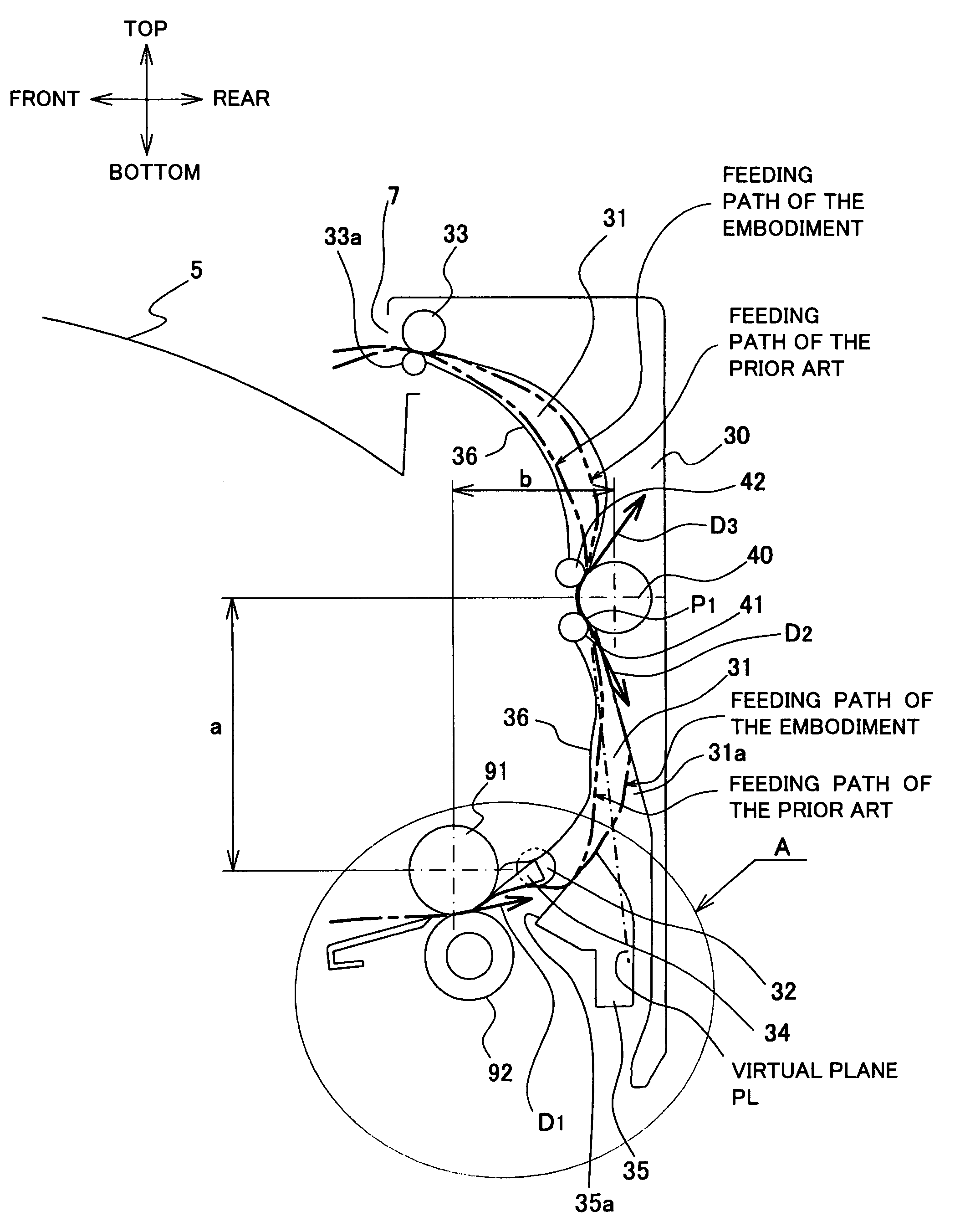
[0009]In view of the above-described points, an aspect of the present invention is to miniaturize the image forming apparatus by turning the feeding direction of the recording medium discharged from the heating roller by approximately 90°, while suppressing a generation of curl in the recording medium.
[0011]According to this structure, tension does not act on the recording medium present between the heating roller and the first discharge roller. Therefore, the recording medium is not pressed against the turning unit, and the curvature of the recording medium in the turning unit becomes smaller (bending radius becomes larger). Accordingly, a large bending stress is not generated in the recording medium, and therefore the curl can be prevented from generating in the recording medium.

Problems solved by technology

Therefore, permanent distortion generates in the curved part, leading to a curl in the recording medium.
Therefore, further larger bending stress is generated in the curved part, resulting in generating a large curl in the recording medium.

Method used


Image

  • Image forming apparatus
  • Image forming apparatus
  • Image forming apparatus

Examples


Embodiment Construction

[0017]Preferred embodiments of a laser printer as an image forming apparatus will be explained based on the drawings hereafter.

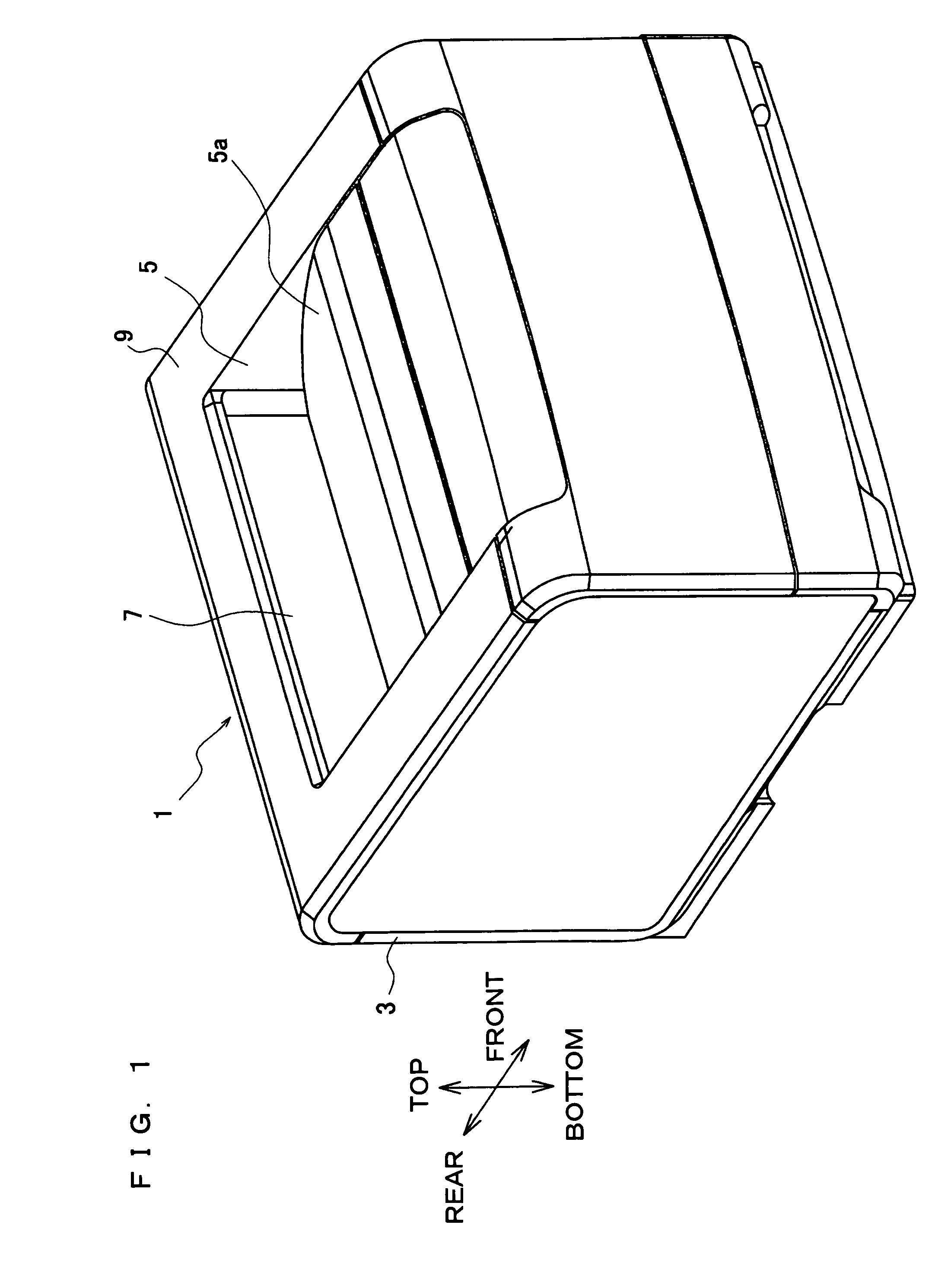
[0018]As shown in FIG. 1, a case body 3 of a laser printer 1 is formed into approximately a box shape (cubic body), and a discharge tray 5 is provided on the upper side of the case body 3, on which a recording medium discharged from the case body 3 after completion of printing is placed. Note that sheets such as a normal paper and an OHP sheet are assumed in this embodiment as the recording medium.

[0019]The discharge tray 5 includes an inclined plane 5a that inclines so that a placing portion is lowered backward. In the vicinity of a rear end of the inclined plane 5a, a discharge section 7 is provided, from which the recording medium after completion of printing is discharged.

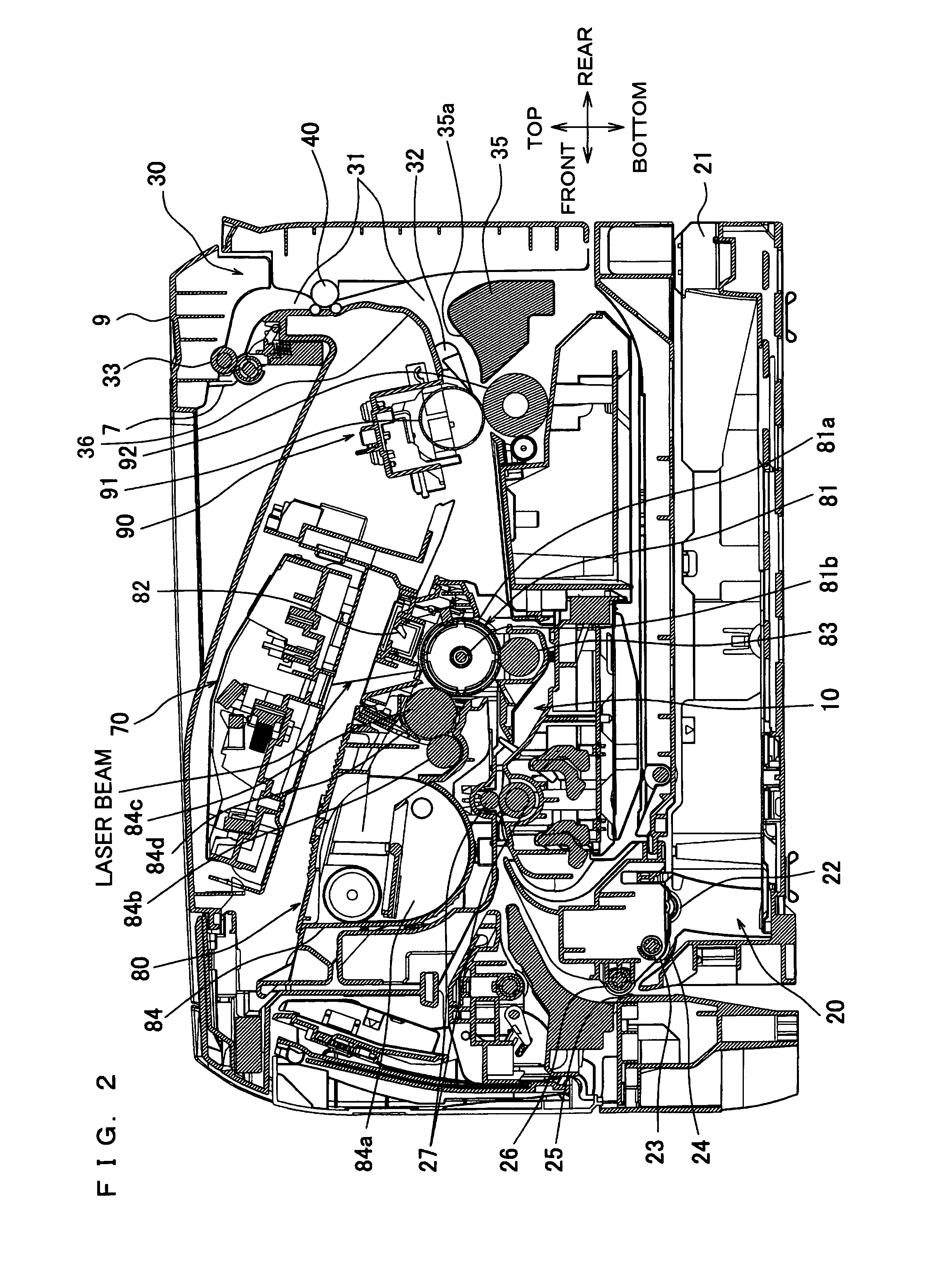
[0020]FIG. 2 is a lateral sectional view showing an essential part of the laser printer 1. An image forming unit 10 constitutes an image forming part for forming an image on the recordi...


PUM


Abstract

An image forming apparatus includes a turning unit that turns the recording medium fed from a fixing unit, which fixes toner transferred to a recording medium and has a heating roller for heating toner, by approximately 90° with respect to a feeding direction of the recording medium, and a discharge roller that discharges the recording medium turned by the turning unit. A circumferential speed of the discharge roller is smaller than a circumferential speed of the heating roller.

Description

CROSS-REFERENCE TO RELATED APPLICATION[0001]This nonprovisional application claims priority under 35 U.S.C, §119(a) on Japanese Patent Application Laid-Open No. 2005-279989 on Sep. 27, 2005, the entire contents of which are hereby incorporated by reference.BACKGROUND[0002]An electrophotographic image forming apparatus forms an image on a recording medium, in such a manner that while rotating a photoreceptor drum, toner stuck on a cylindrical surface thereof is transferred to a recording medium, such as normal paper and OHP paper, and by heating the toner thus transferred to the recording medium by a heating roller, the toner is fixed to the recording medium.[0003]However, when the recording medium is heated by the heating roller, thermal shrinkage of a surface of the recording medium on the side of the heating roller occurs. Therefore, the recording medium is easily curled along the heating roller.[0004]In order to prevent such a curl, for example, according to the invention disclos...

Claims


Application Information

Patent Timeline
Patent Type & Authority Patents(United States)
IPC IPC(8): B41J2/05
CPCG03G15/6573G03G2215/00696
Inventor MATSUNO, TAKUJI
Owner BROTHER KOGYO KK
Learn More