
Steering system motor

a steering system and motor technology, applied in the field of motors, can solve the problems of motor failure, rotor vibrating, and of course the inability to steer, and achieve the effect of improving the failure-safe performan

Inactive Publication Date: 2010-10-05
TOYOTA JIDOSHA KK
View PDF10 Cites 11 Cited by
  • Summary
  • Abstract
  • Description
  • Claims
  • Application Information

AI Technical Summary

Benefits of technology

The invention provides a steering system motor that is better suited for practical use compared to conventional motors. It has improved fail-safe performance and reduced vibration during normal operation. The motor includes a stator with multiple magnetic pole bodies that generate magnetism when power is supplied to them. Each magnetic pole body is divided into groups, and each group has its own power supply portion. This ensures that power is independently supplied to each group, and that the forces exerted on the rotor by the magnetic pole bodies cancel out, reducing vibration. The motor is also designed to alert the driver if one of the systems fails, ensuring continued safe operation.

Problems solved by technology

When the system on one side fails, magnetism is generated by the other system on the other side, which causes the rotor to vibrate.
This vibration alerts the driver that the motor has failed.
With the electromagnetic motor described in JP-A-7-222419, if the single system starter fails, steering assist is of course disabled, i.e., the wheels are no longer able to be steered by the motor.
Thus, the motor is not considered very reliable.
However, because it is difficult to accurately synchronize the power of the two systems, a relatively small vibration tends to be generated even when both systems are operating normally.
This problem may make it difficult to enhance the practical use of a conventional steering system motor.

Method used


Image

  • Steering system motor
  • Steering system motor
  • Steering system motor

Examples


Embodiment Construction

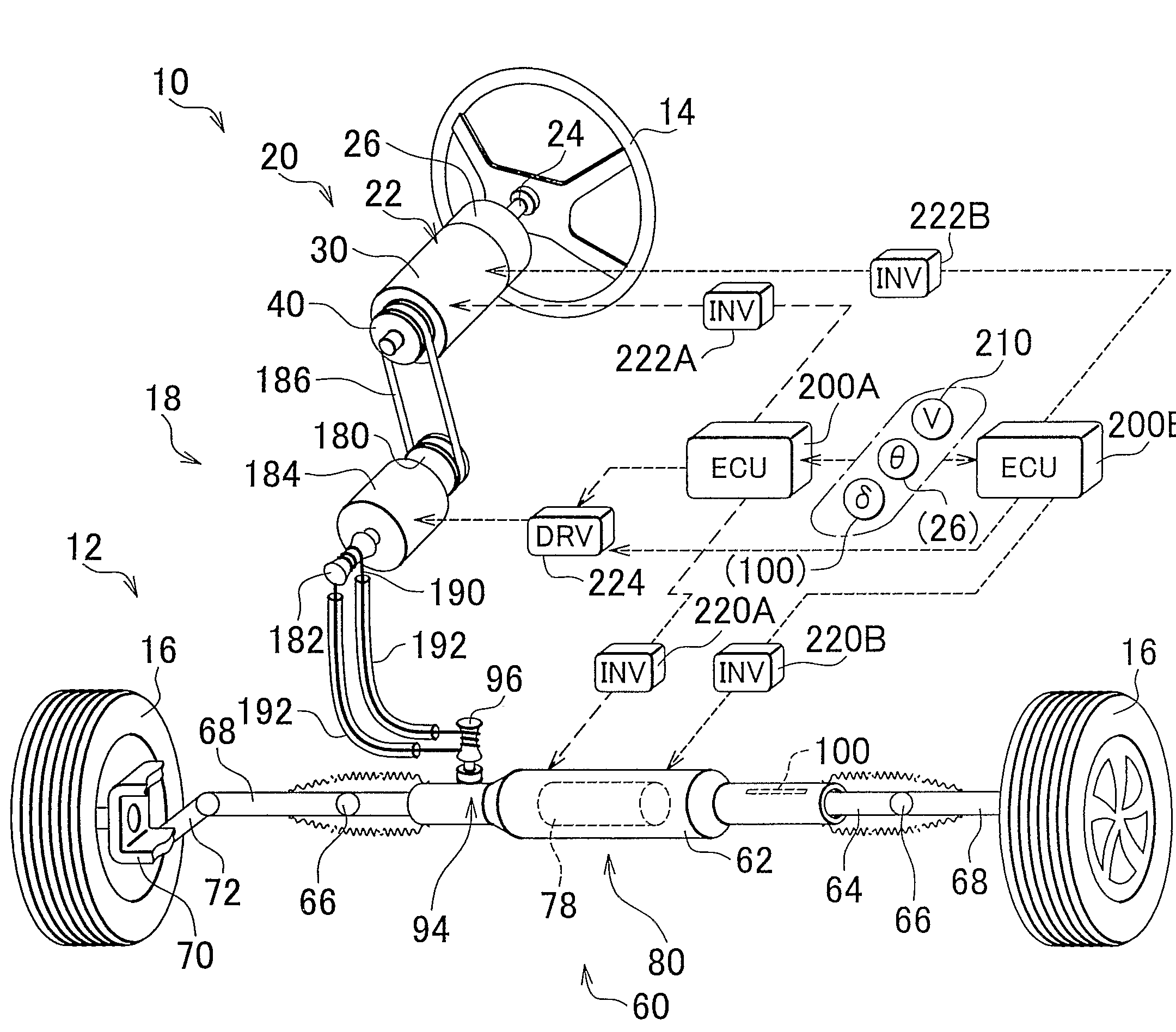
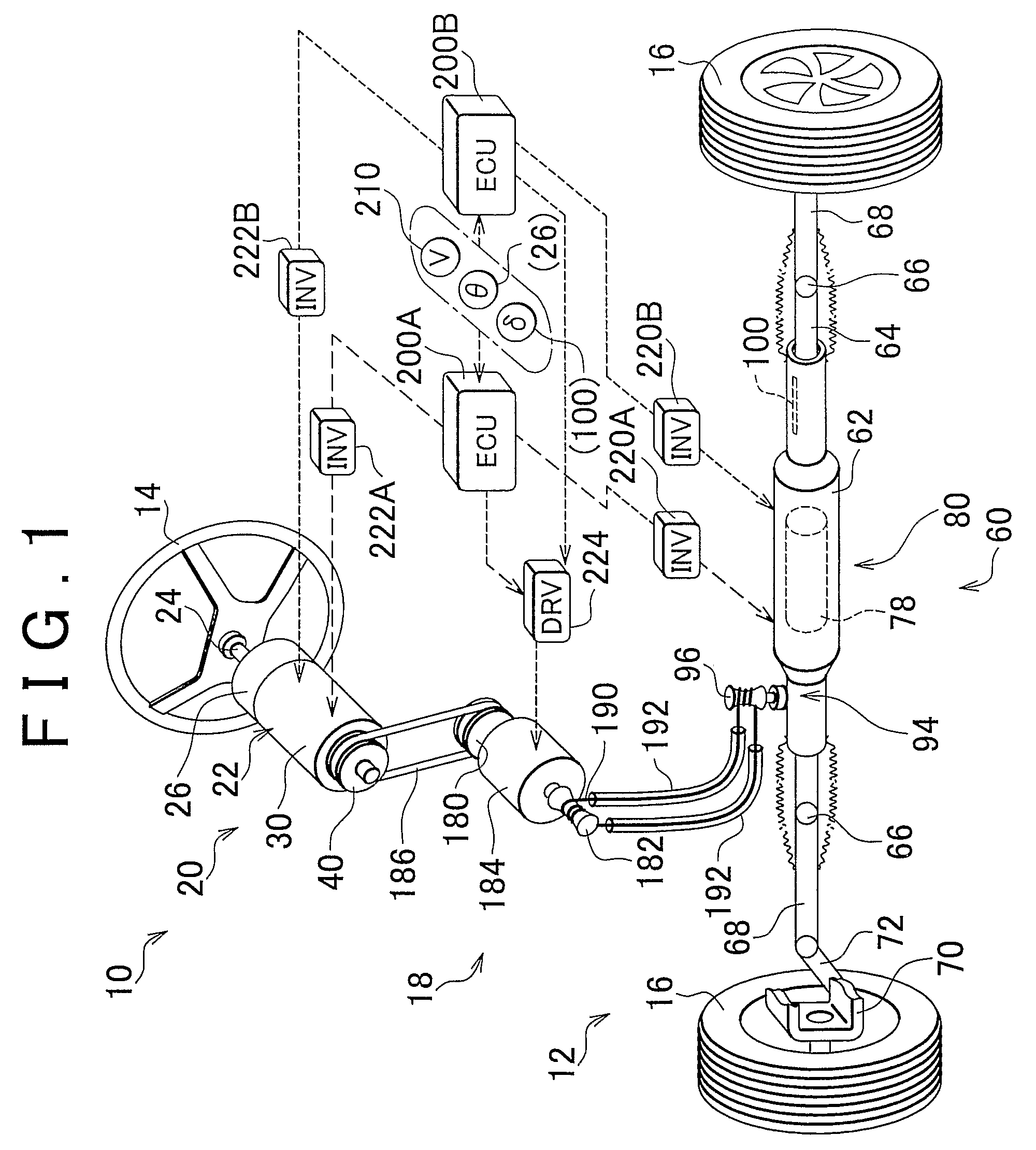
[0035]FIG. 1 is a schematic diagram of a steering system provided with a steering system motor according to one example embodiment of the invention. This steering system is mechanically divided into an operating portion 10 and a steering portion 12. The steering system detects operation of a steering wheel 14, which serves as an operating member, and steers the steered wheels 16 (hereinafter simply referred to as “wheels 16”) with the driving force of the steering portion 12 by electrically controlling the steering portion 12 based on the detected operation instead of the operating force of the steering wheel 14. The steering system also includes a connecting portion 18 that mechanically connects the operating portion 10 and the steering portion 12 together when necessary so that the operating force is communicated to the steering portion 12.

[0036]The operating portion 10 includes the steering wheel 14 and a steering reaction-force application apparatus 20, which both supports the s...


PUM


Abstract

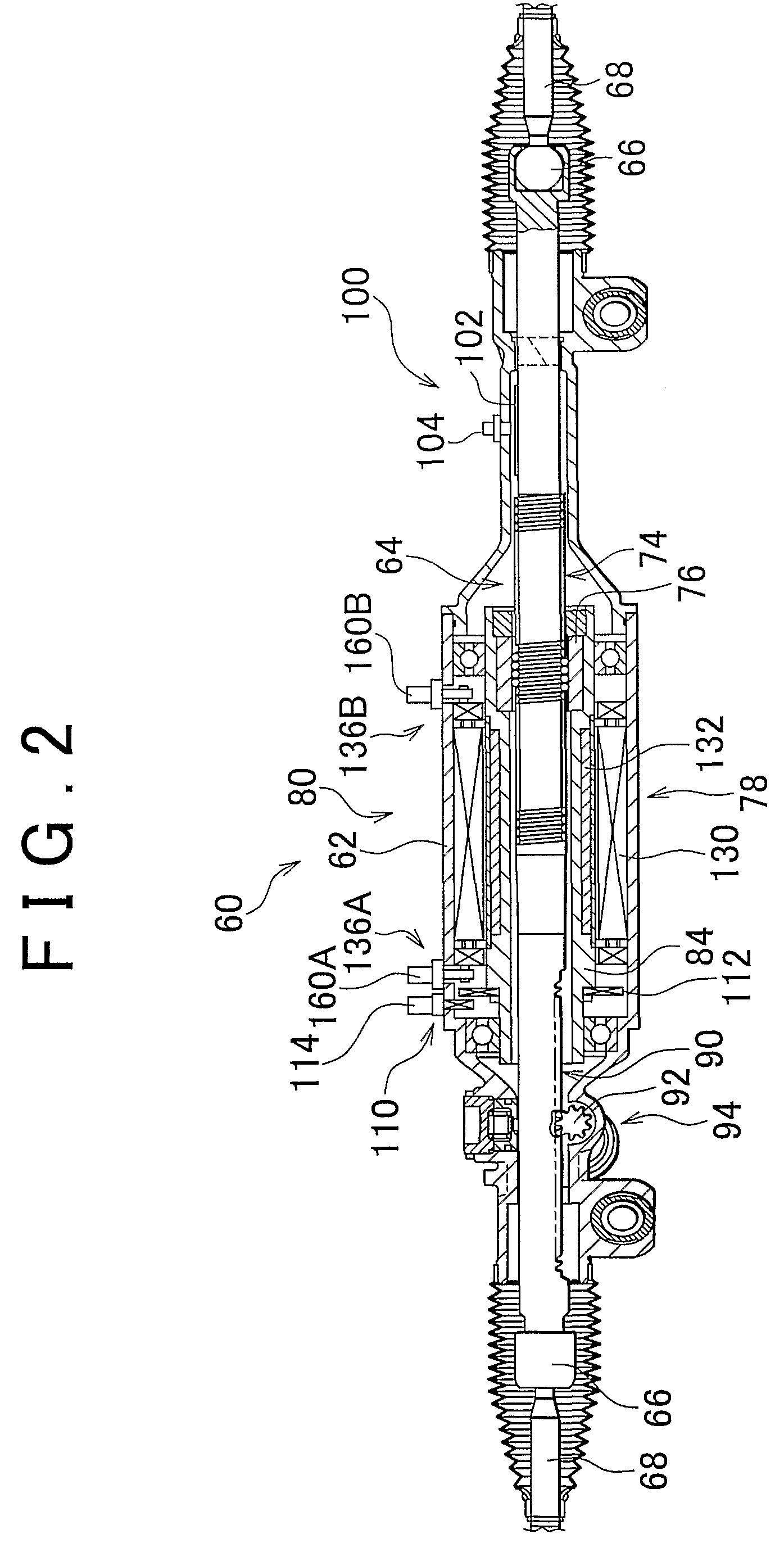
A plurality of magnetic pole bodies, provided on a stator of a steering motor, are divided into two electrically independent groups. Each group includes i) six magnetic pole bodies that are arranged in succession and ii) a corresponding number of magnetic pole bodies arranged opposing those six magnetic pole bodies. The two groups vibrate only slightly when operating normally. However, if one of the groups fails, vibration of the stator from elastic deformation in an undulating manner in the circumferential direction will increase, thereby alerting the driver of an abnormality in the steering motor. This increases the likelihood of measures being taken promptly to fix the abnormality in the steering motor, thus improving fail-safe performance.

Description

BACKGROUND OF THE INVENTION[0001]1. Field of the Invention[0002]The invention relates to a motor provided in a steering system, and more particularly, to a steering system motor in which a starter of the motor is divided into a plurality of systems that are electrically independent from one another.[0003]2. Description of the Related Art[0004]Examples of a steering system motor include a motor, which serves as a power source for assisting with steering, and a motor, which serves as a power source for steering wheels. A vehicle is typically provided with a system for assisting with steering, i.e., a power steering system. The motor of a power steering system is sometimes an electromagnetic motor that is mounted, for example, near the steering column or a rack-and-pinion mechanism. Also, in a steer-by-wire type steering system, in which the wheels are steered by controlling a power source of a steering portion, the operating force that is input to an operating member, such as a steeri...

Claims


Application Information

Patent Timeline
Patent Type & Authority Patents(United States)
IPC IPC(8): B26D5/08
CPCB62D5/0403H02K3/28H02K16/04
Inventor ITOH, KOICHI
Owner TOYOTA JIDOSHA KK
Learn More