Aircraft wing, aircraft wing composite material, and method of manufacture thereof

a technology of aircraft wings and composite materials, which is applied in the direction of aircraft floors, fuselages, aircraft wing shapes, etc., can solve the problems of insufficient strength in the wing chord direction to achieve the application of morphing aircraft technology, and the inability to achieve high bending flexibility in the wing chord direction, and achieve high bending flexibility and high capacity. , the effect of high capacity

Inactive Publication Date: 2010-09-28
JAPAN AEROSPACE EXPLORATION AGENCY
View PDF8 Cites 14 Cited by
  • Summary
  • Abstract
  • Description
  • Claims
  • Application Information

AI Technical Summary

Benefits of technology

[0013]From the viewpoint of the forgoing problems, it is an object of the present invention to provide an aircraft wing which has both high bending flexibility in the wing chord direction and high load bearing capacity and high capacity to maintain the wing shape in the wing span direction, and to which morphing aircraft technology can be applied in the high-speed regime where aerodynamic forces are high. And it is also an object of the present invention to provide an aircraft wing composite material of the wing and method of manufacture thereof.

Problems solved by technology

Therefore, high bending flexibility in the wing chord direction together with high capacity to maintain the wing shape in the wing span direction is not achieved.
The other wings also do not achieve high bending flexibility in the wing chord direction together with high capacity to maintain the wing shape in the wing span direction as in the case of the air-filled wings.
As a result, the optimum stiffness ratio (Dc:Ds) is 1:15 at most, which is insufficient for application to a wing for morphing aircraft technology where the stiffness requirement is Dc:Ds=1:100 or greater.
At the stiffness level, the strength in the wing chord direction is also insufficient for the application of morphing aircraft technology.
However, in unidirectionally reinforced rubber materials the compressive strength of the wing is low in the fiber direction, in other words, the wing span direction.
Therefore, there is a problem of loss of load bearing capacity in the above wings made from CFRR due to bending forces caused by aerodynamic forces in the high-speed regime where aerodynamic forces are high.

Method used


Image

  • Aircraft wing, aircraft wing composite material, and method of manufacture thereof
  • Aircraft wing, aircraft wing composite material, and method of manufacture thereof
  • Aircraft wing, aircraft wing composite material, and method of manufacture thereof

Examples


first embodiment

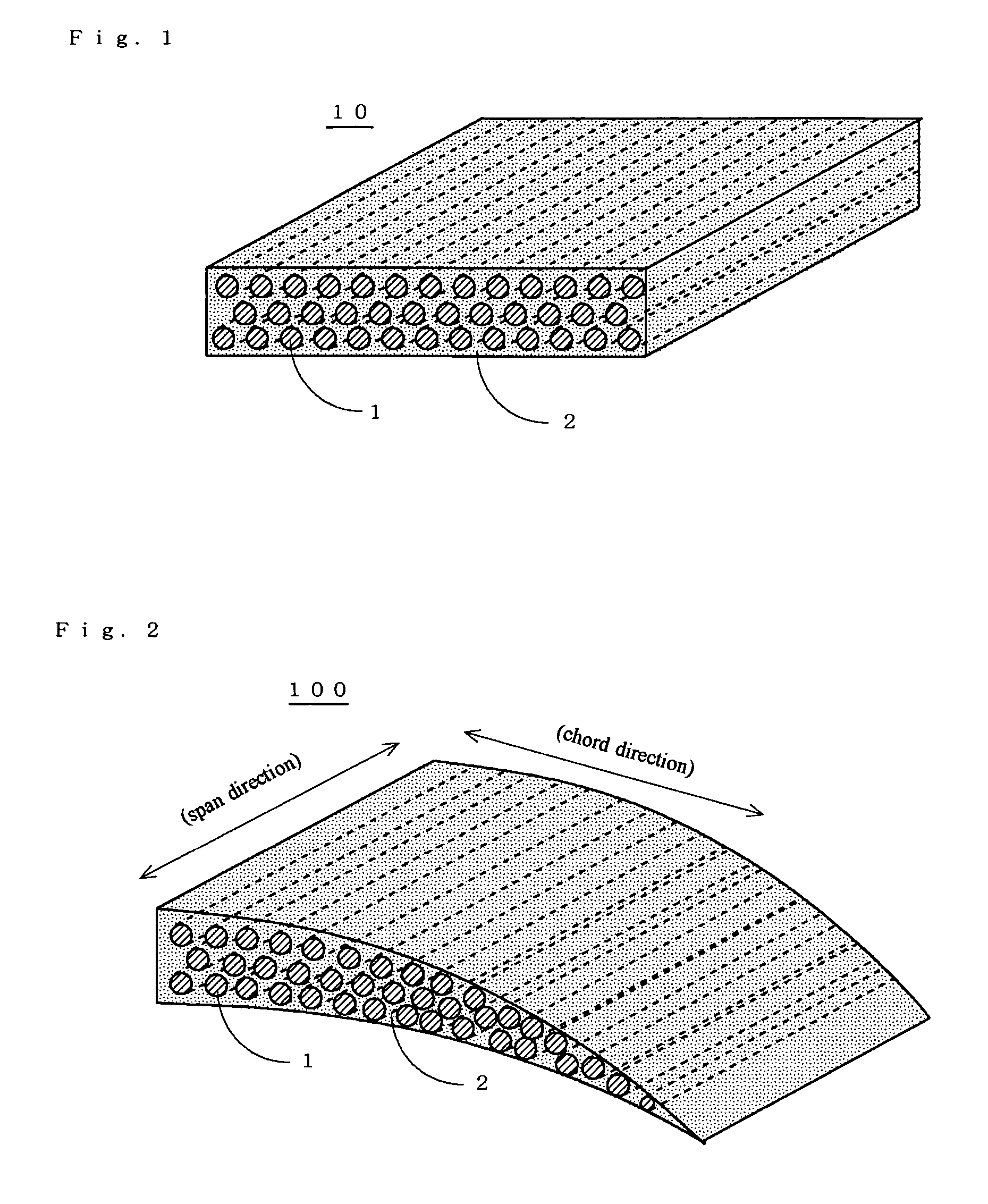
[0096]FIG. 1 is a perspective view showing the cross-section of the main portion of an aircraft wing composite material 10 according to a first embodiment of the present invention.

[0097]This aircraft wing composite material 10 comprises carbon fiber-reinforced plastic (hereafter referred to as CFRP) rods 1 made from CFRP material with the anisotropic stiffness in the axial direction, and an elastic material 2 filling the gaps between the CFRP rods 1.

[0098]This aircraft wing composite material 10 is obtained by the manufacturing method where the CFRP rods 1 are firstly made by arranging the carbon fibers in axial direction and then, the CFRP rods 1 are laid in the same direction and then, the gaps between the CFRP rods 1 are impregnated with the precursor of the elastic material 2 and hardened. The elastic material 2 is a silicone rubber, for example.

[0099]FIG. 2 is a perspective view showing the cross-section of the main portion of an aircraft wing 100 according to a first embodimen...

second embodiment

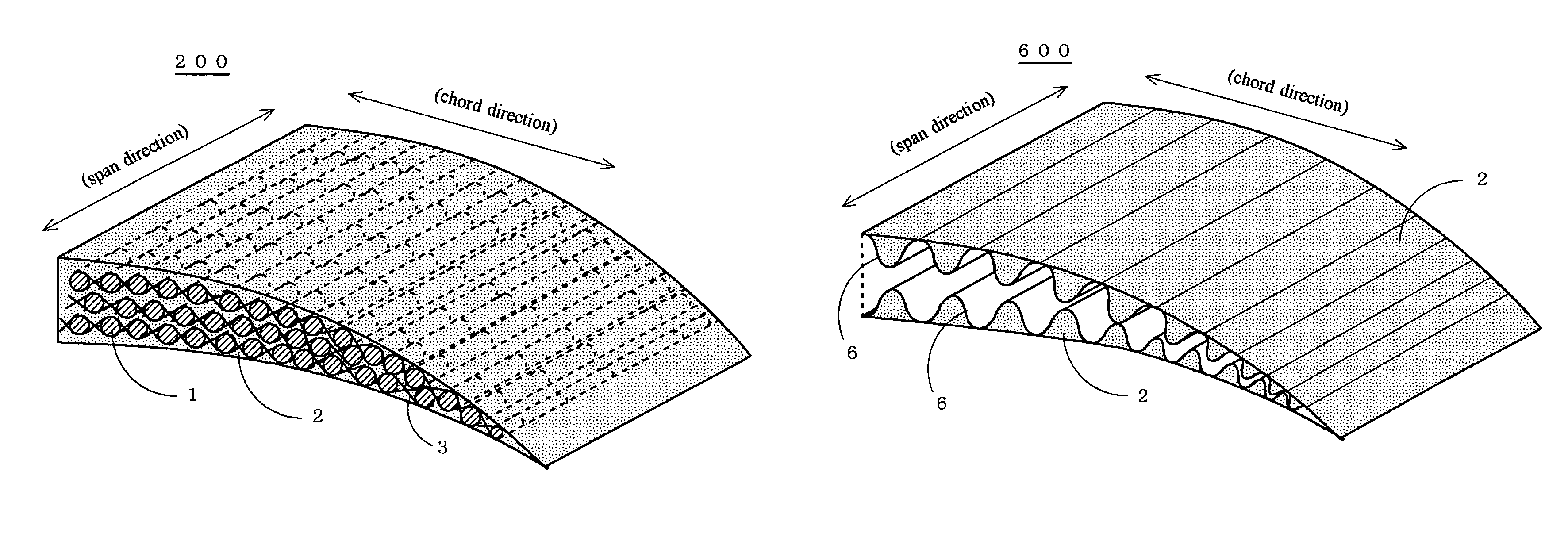
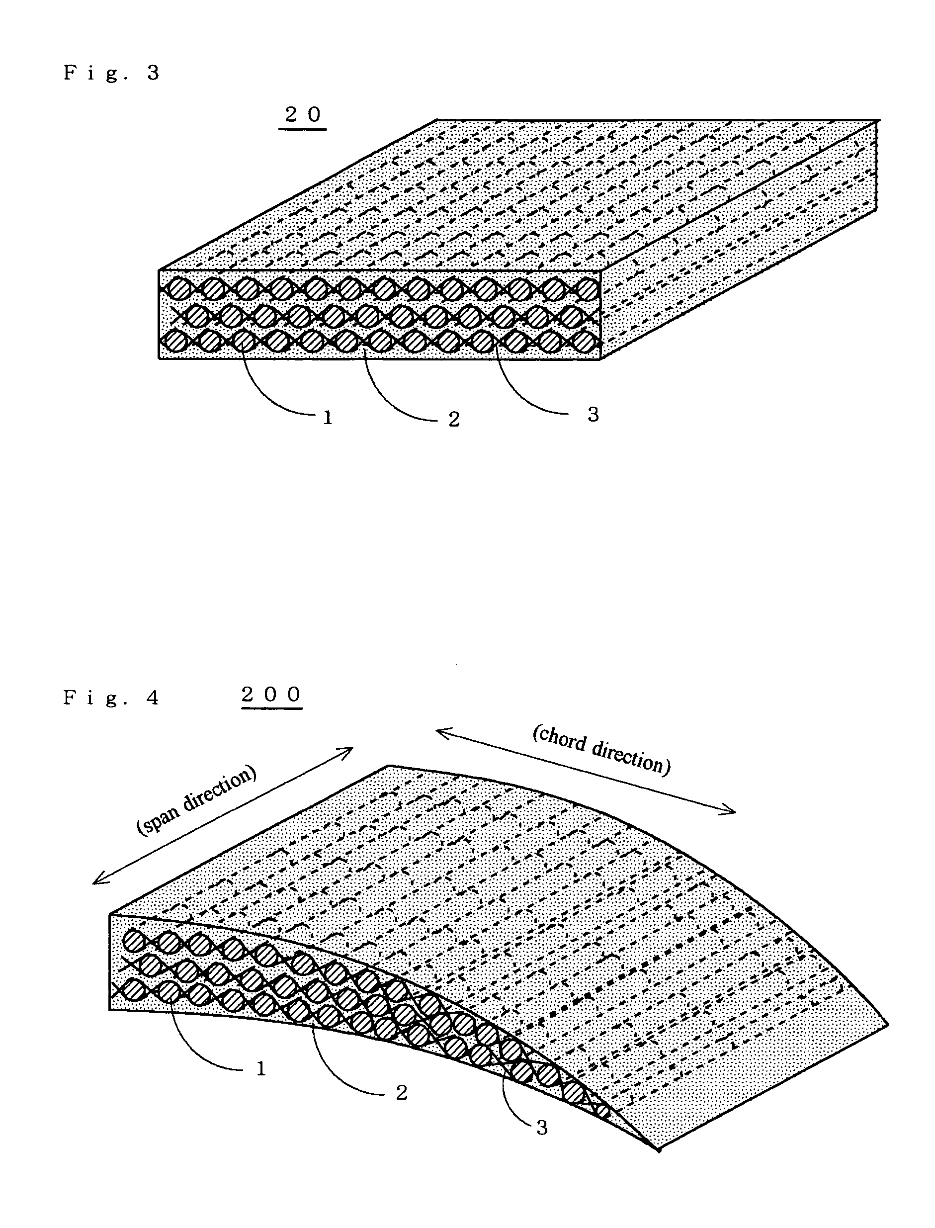
[0102]FIG. 3 is a perspective view showing the cross-section of the main portion of an aircraft wing composite material 20 according to a second embodiment of the present invention.

[0103]This aircraft wing composite material 20 comprises CFRP rods 1 with the anisotropic stiffness in the axial direction, an elastic material 2 filling the gaps between the CFRP rods 1, and yarn 3 binding the CFRP rods 1. The elastic material 2 is a silicone rubber, for example, and the yarn 3 is spun aramide fiber, for example.

[0104]This aircraft wing composite material 20 is obtained by the manufacturing method where the CFRP rods 1 are firstly made by arranging the carbon fibers in axial direction and then, the CFRP rods 1 are laid in the same direction and then, the CFRP rods 1 are constructed into the form of a blind using the yarn 3 and then, the CFRP rods 1 constructed into the form of a blind are piled in a plurality of layers and then, the gaps between the CFRP rods 1 are impregnated with the p...

third embodiment

[0108]FIG. 5 is a perspective view showing the cross-section of the main portion of an aircraft wing composite material 30 according to a third embodiment of the present invention.

[0109]This aircraft wing composite material 30 comprises CFRP rods 1 with the anisotropic stiffness in the axial direction, an elastic material 2 filling the gaps between the CFRP rods 1, yarn 3 binding the CFRP rods 1 in the form of a blind, and binding yarn 4 for binding together the yarn 3.

[0110]This aircraft wing composite material 30 is obtained by the manufacturing method where the CFRP rods 1 are firstly made by arranging the carbon fibers in axial direction and then, the CFRP rods 1 are laid in the same direction and then, the CFRP rods 1 are constructed into the form of a blind using the yarn 3 and then, the CFRP rods 1 constructed into the form of a blind are piled in a plurality of layers and then, the yarn 3 is bound with the binding yarn 4 together and then, the gaps between the CFRP rods 1 ar...


PUM


Abstract

To provide an aircraft wing which has both high bending flexibility in the wing chord direction and high capacity to maintain the wing shape in the wing span direction, and to which morphing aircraft technology can be applied in the high-speed regime where aerodynamic forces are high.The wing is formed by arranging a plurality of CFRP rods having maximum anisotropic stiffness in the axial direction, so as to be parallel to the wing span direction, and filling the gaps between the CFRP rods with an elastic material.

Description

BACKGROUND OF THE INVENTION[0001]1. Field of the Invention[0002]The present invention relates to an aircraft wing, aircraft wing composite material, and method of manufacture thereof. More particularly the present invention relates to an aircraft wing which has both high bending flexibility in the wing chord direction and high load bearing capacity and high capacity to maintain the wing shape in the wing span direction, and to which morphing aircraft technology can be applied in the high-speed regime where aerodynamic forces are high. The present invention also relates to an aircraft wing composite material and method of manufacture thereof.[0003]2. Description of the Related Art[0004]Research and development into technology, in which the shape of wings can be changed arbitrarily to improve the flight performance and characteristics of aircraft just like birds (hereinafter referred to as “morphing aircraft technology”), is being carried out mainly in the USA. Aircraft wings to which...

Claims


Application Information

Patent Timeline
Patent Type & Authority Patents(United States)
IPC IPC(8): B64C3/26
CPCB64C3/48
Inventor ISHIKAWA, TAKASHIIWAHORI, YUTAKAYOKOZEKI, TOMOHIROTAKEDA, SHIN-ICHI
Owner JAPAN AEROSPACE EXPLORATION AGENCY
Why Eureka
Try Eureka