
Internal combustion engine having variable valve operating device

a technology of operating device and internal combustion engine, which is applied in the direction of valve drive, mechanical control device, instruments, etc., can solve the problem of taking a large space, and achieve the effect of efficient actuator layou

Inactive Publication Date: 2010-09-28
HONDA MOTOR CO LTD
View PDF13 Cites 6 Cited by
  • Summary
  • Abstract
  • Description
  • Claims
  • Application Information

AI Technical Summary

Benefits of technology

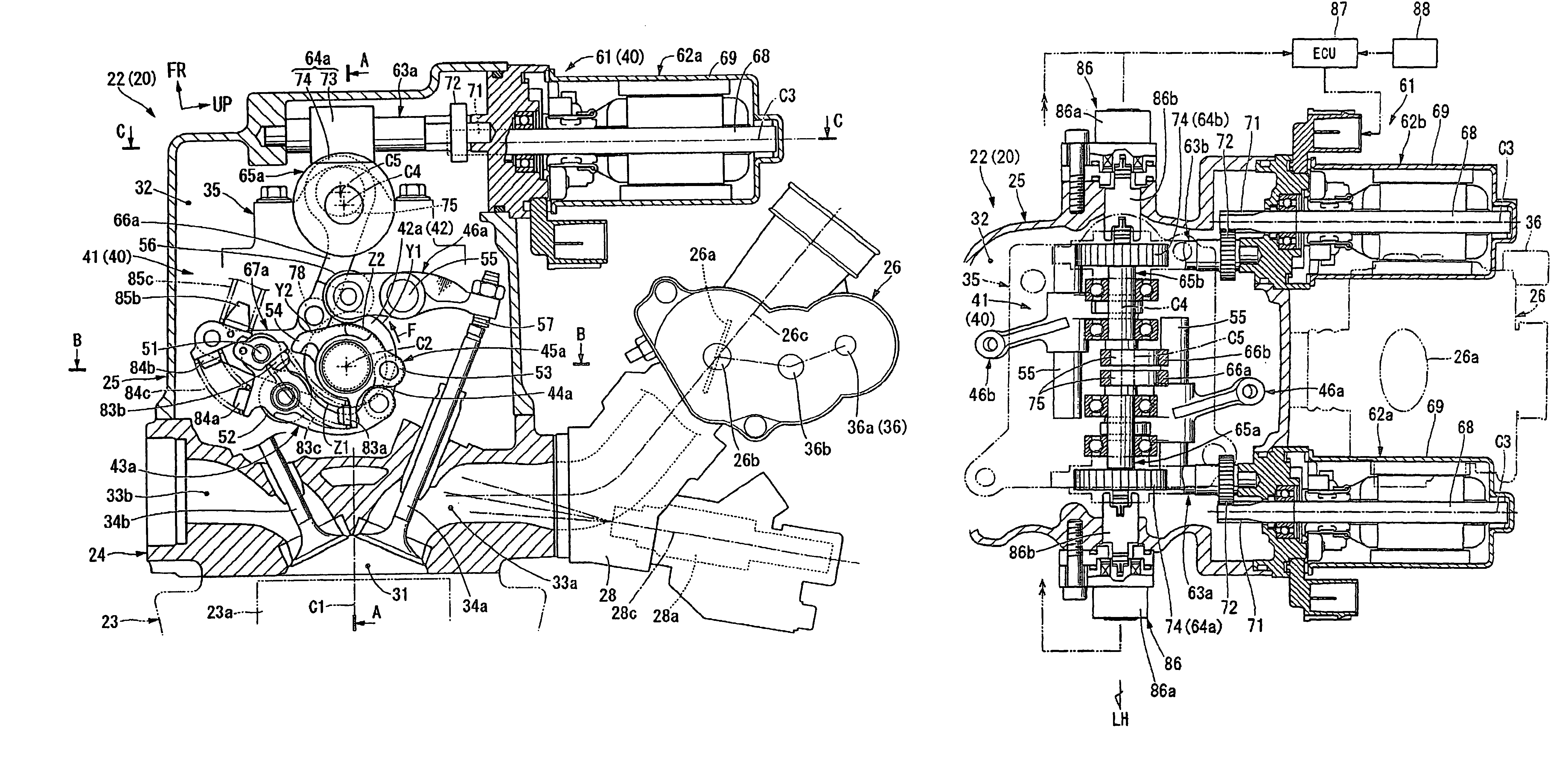
[0008]Accordingly, it is an object of an embodiment of the present invention, in an internal combustion engine having a variable valve operating device which controls valve operating characteristic thereof, to enable individual controls of an intake valve and an exhaust valve and an efficient layout of an actuator for the control.

Problems solved by technology

Since the actuator becomes bulky or takes a relatively large space, the actuator is usually arranged outside a valve operating chamber separately from respective parts of the mechanism.
However, in such a case, it is necessary to sufficiently study a layout of the actuator which is liable to take a large space.

Method used


Image

  • Internal combustion engine having variable valve operating device
  • Internal combustion engine having variable valve operating device
  • Internal combustion engine having variable valve operating device

Examples


Embodiment Construction

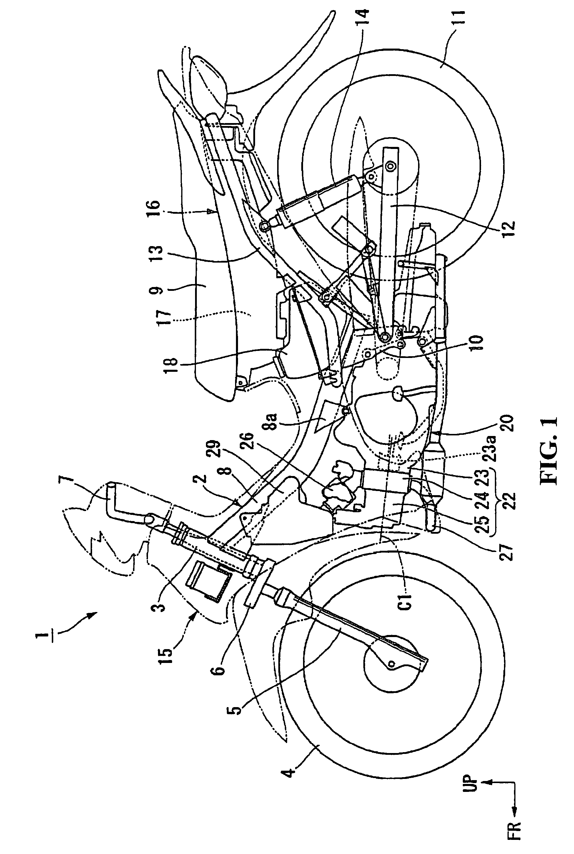
[0034]Hereinafter, embodiments of the present invention are explained in conjunction with the drawings. In the explanation made hereinafter, the directions of front, rear, left, right and the like are, unless otherwise specified, equal to directions of the vehicle. Further, in the drawing, an arrow FR indicates the frontward direction of the vehicle, an arrow LH indicates the leftward direction of the vehicle, and an arrow UP indicates the upward direction of the vehicle respectively.

[0035]In a motorcycle 1 shown in FIG. 1, left and right front forks 5 pivotally support a front wheel 4 that is steerably supported on a head pipe 3 which is positioned on a front end portion of a vehicle body frame 2 by way of a steering stem 6. A bar handle 7 for steering is mounted on an upper portion of the steering stem 6. A right grip portion of the bar handle 7 forms a throttle grip.

[0036]The vehicle body frame 2 is of a so-called backbone type in which one main tube 8 extends rearwardly and down...


PUM


Abstract

To effectively arrange actuators for control by individually controlling an intake valve and an exhaust valve in an internal combustion engine which includes a variable valve operating device for controlling valve operating characteristics. An internal combustion engine includes a variable valve operating device having a valve characteristic variable mechanism for controlling valve operating characteristics of engine valves consisting of an intake valve and an exhaust valve. The valve characteristic variable mechanism includes electrically operated motors for changing operational timings and lift quantities of the above-mentioned engine valves. The electrically operated motors are arranged outside a valve operating chamber. At the same time, the electrically operated motors are arranged close to the throttle body on a cylinder intake side.

Description

CROSS-REFERENCE TO RELATED APPLICATIONS[0001]The present application claims priority under 35 USC 119 to Japanese Patent Application No. 2006-219699 filed on Aug. 11, 2006 the entire contents of which are hereby incorporated by reference.BACKGROUND OF THE INVENTION[0002]1. Field of the Invention[0003]The present invention relates to an internal combustion engine having a variable valve operating device.[0004]2. Description of Background Art[0005]An internal combustion engine which is mounted on a vehicle is known wherein a valve operating mechanism is provided on a cylinder head with a valve characteristic variable mechanism for controlling the respective operational timings and maximum lift quantities of an intake valve and an exhaust valve. See, for example, JP-A-2005-207254, JP-A-2005-207255, JP-A-2004-27865, JP-A-2002-70596 and JP-A-2000-291419.[0006]The valve characteristic variable mechanism includes a single actuator, an electrically operated motor, a hydraulic cylinder or th...

Claims


Application Information

Patent Timeline
Patent Type & Authority Patents(United States)
IPC IPC(8): F01L1/34
CPCF01L1/022F01L13/0005F01L13/0026F01L1/20Y10T74/20882F01L2013/0073F01L2105/00F01L2820/032F01L2001/0535F01L2305/00
Inventor INOMOTO, YUTAKAKUROKI, MASAHIRO
Owner HONDA MOTOR CO LTD
Learn More