Free fall detector device and free fall detection method
a detector device and detector technology, applied in the direction of acceleration measurement in multiple dimensions, acceleration measurement using interia forces, devices characerised by mechanical means, etc., can solve the problems of conflict or slowing down of operations, the surface of the disk and the read/write head is practically in contact, and the use is very delicate,
- Summary
- Abstract
- Description
- Claims
- Application Information
AI Technical Summary
Benefits of technology
Problems solved by technology
Method used
Image
Examples
second embodiment
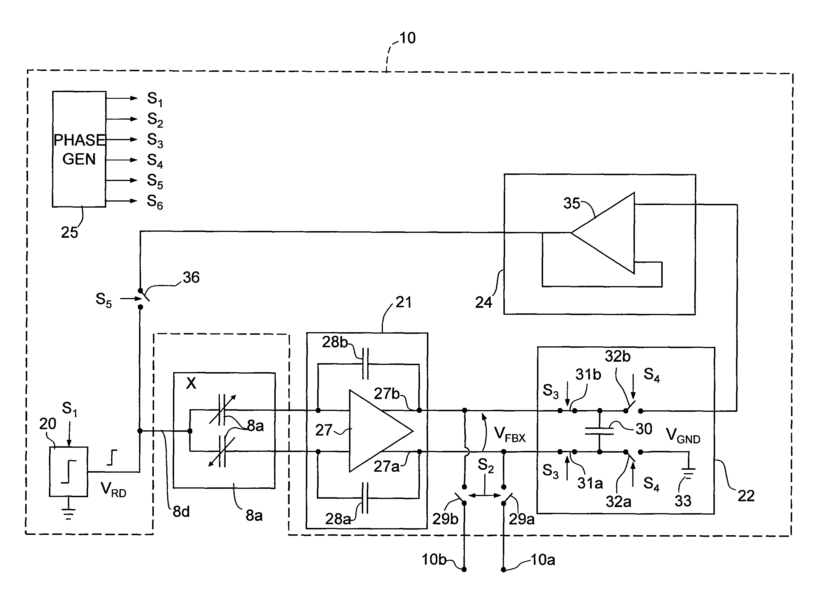
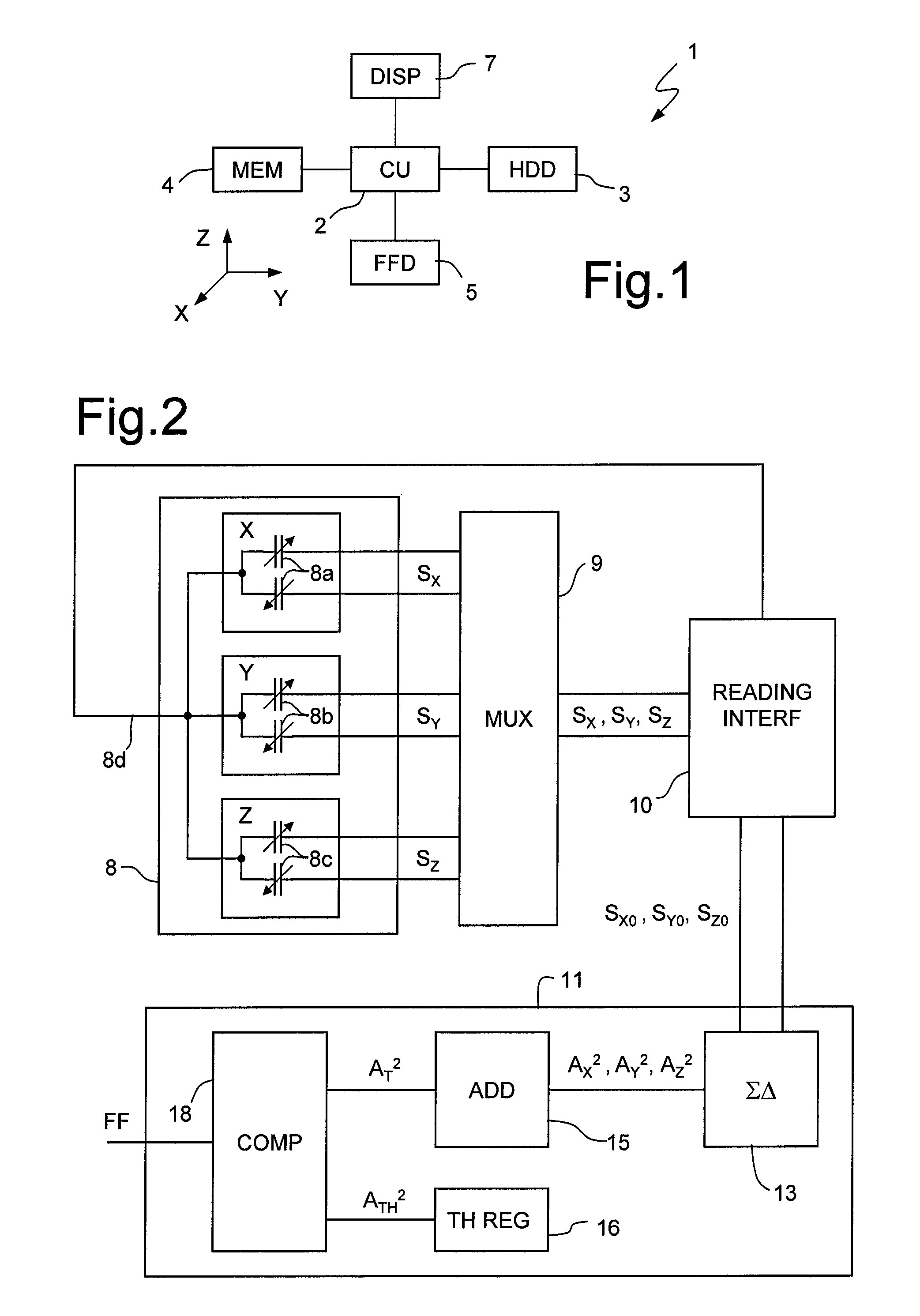
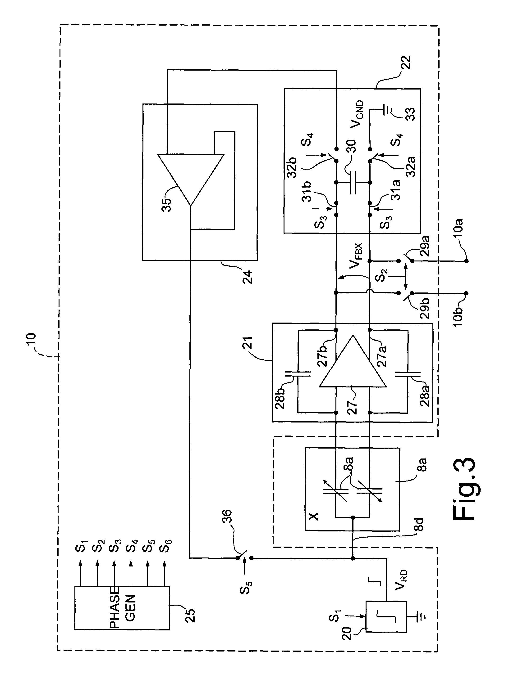
[0054]FIG. 6, in which parts that are the same as those already illustrated are designated by the same reference numbers, shows the invention. In this case, a free-fall detector 100 comprises the inertial sensor 8, the reading interface 10, and a fully analog processing stage111. In greater detail, the processing stage 111 comprises a demultiplexer 112, a first memory capacitor 115a, a second memory capacitor 115b, and a third memory capacitor 155c, a comparator 120 and a reference line 125 supplying a reference threshold signal STHR. The first, second, and third memory capacitors 115a, 115b, 115c are selectively and sequentially connectable to the outputs 10a, 10b of the reading interface 10 by the demultiplexer 112 for receiving, respectively, the first, second and third detection signals SXO, SYO, SZO, which are proportional to the square of the moduli of the acceleration components detected by the inertial sensor 8 according to the first, second, and third detection axes X, Y, Z...
third embodiment
[0058]FIGS. 7 and 8, in which parts already illustrated are again designated by the same reference numbers, show the invention.
[0059]In this case, a free-fall detector 200 comprises an inertial sensor 208, a multiplexer 209, a reading interface 210, and the processing stage 11.
[0060]The inertial sensor 208 is again a linear accelerometer of a capacitive MEMS type with mutually perpendicular and independent first, second, and third detection axes X, Y, Z. In FIG. 7, the inertial sensor 208 is represented schematically by a first, second, and third pair of capacitors 208a, 208b, 208c having variable capacitance in response to forces and accelerations acting on the inertial sensor 8 according to the first, second, and third detection axes X, Y, Z, respectively.
[0061]In this case, each pair of capacitors 208a, 208b, 208c has a terminal in common, connected to a detection terminal 208d of the inertial sensor 8, and two driving terminals, selectively and sequentially connectable to drivin...
PUM
 Abstract
Description
Claims
Application Information
 - R&D
- Intellectual Property
- Life Sciences
- Materials
- Tech Scout
- Unparalleled Data Quality
- Higher Quality Content
- 60% Fewer Hallucinations
Browse by: Latest US Patents, China's latest patents, Technical Efficacy Thesaurus, Application Domain, Technology Topic, Popular Technical Reports.
© 2025 PatSnap. All rights reserved.Legal|Privacy policy|Modern Slavery Act Transparency Statement|Sitemap|About US| Contact US: help@patsnap.com


