Electrohydraulic valve control circuit with velocity fault detection and rectification

a control circuit and electrohydraulic valve technology, applied in hydrodynamic testing, instruments, structural/machine measurement, etc., can solve problems such as adverse consequences, require corrective action, and unsafe machine operation

Inactive Publication Date: 2010-09-14
HUSCO INT INC
View PDF4 Cites 0 Cited by
  • Summary
  • Abstract
  • Description
  • Claims
  • Application Information

AI Technical Summary

Benefits of technology

[0011]Integrating the velocity error value ensures that an over speed or an under speed condition must persist for a defined period of time before a velocity fault is declared. In a preferred implementation, the integrating is accomplished by a biquadratic filter function which decreases the integrated value for error frequencies that are below a cutoff frequency.

Problems solved by technology

Such errors may result in an unsafe operation of the machine and thus require corrective action.
However, such detection must be sufficiently robust to avoid erroneously declaring a fault condition because taking corrective action during normal machine action also may have adverse consequences.

Method used


Image

  • Electrohydraulic valve control circuit with velocity fault detection and rectification
  • Electrohydraulic valve control circuit with velocity fault detection and rectification
  • Electrohydraulic valve control circuit with velocity fault detection and rectification

Examples


Embodiment Construction

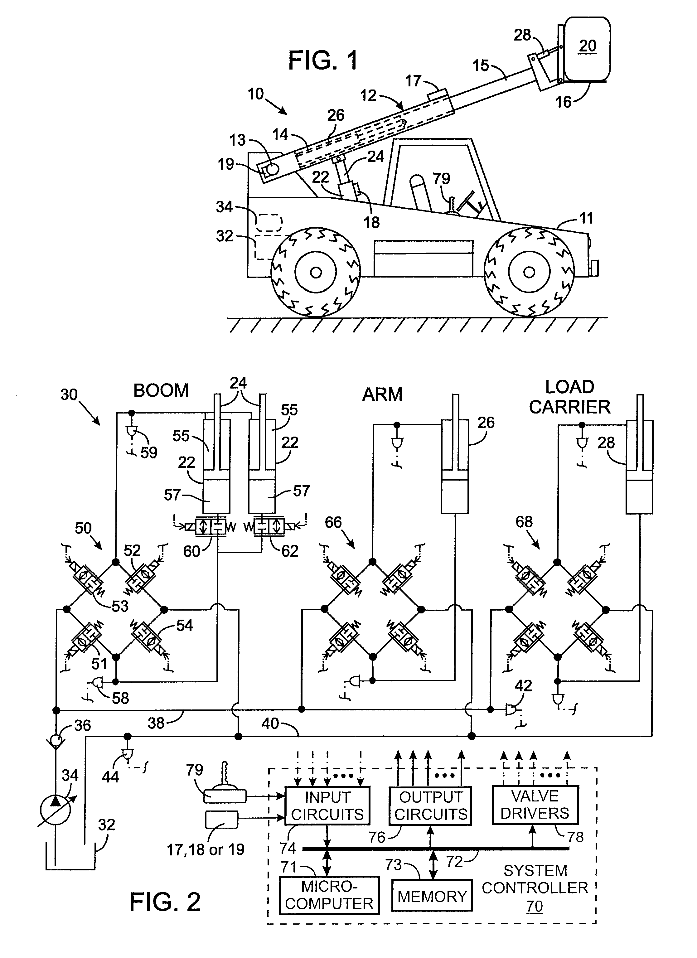
[0016]With initial reference to FIG. 1, a telehandler 10 is an example of a machine on which the present invention can be used, with the understanding that the invention has application to a wide variety of machines. The telehandler 10 has a carriage 11 with an operator cab. The carriage 11 supports an engine or battery powered motors (not shown) for driving the wheels across the ground and for powering a hydraulic system. A boom assembly 12 comprises a boom 14, an arm 15, and a load carrier 16. The boom 14 is pivotally attached to the rear of the carriage 11 and is raised and lowered by a boom hydraulic actuator 21, in this case a pair of boom cylinders 22 each having a piston rod 24 (only one cylinder / piston rod arrangement is visible in FIG. 1). An arm hydraulic actuator 26 causes the arm 15 to slide telescopically within the boom 14 thereby extending and retracting the length of the boom assembly 12. The load carrier 16 is pivotally mounted at the remote end of the arm 15 and ma...


PUM


Abstract

Motion of a hydraulically driven machine component is controlled in response to a velocity command that indicates a desired velocity for the machine component. A method for detecting a velocity fault involves determining an actual velocity at which the machine component is moving, and producing a velocity error value based on a difference between the velocity command and the actual velocity. The velocity error value is integrated, such as by a low pass, biquadratic filter function, to produce an integrated value. The integrated value is compared to one or more thresholds to determine whether a velocity fault has occurred.

Description

CROSS-REFERENCE TO RELATED APPLICATIONS[0001]This application claims benefit of U.S. Provisional Patent Application No. 60 / 821,877 filed on Aug. 9, 2006.STATEMENT REGARDING FEDERALLY SPONSORED RESEARCH OR DEVELOPMENT[0002]Not ApplicableBACKGROUND OF THE INVENTION[0003]1. Field of the Invention[0004]The present invention relates to hydraulic power systems with electrically operated valves that control fluid flow to hydraulically drive actuators, and more particularly to mechanisms that detect faults occurring in such systems.[0005]2. Description of the Related Art[0006]A wide variety of machines have moveable elements that are driven by a hydraulic actuator, such as a cylinder and piston arrangement. For example, a telehandler has a tractor on which a telescopic boom is mounted with a load carrier pivotally attached to the remote end of the boom. The telescopic boom and the load carrier are moved with respect to the tractor by hydraulic actuators. The flow of fluid to and from each h...

Claims


Application Information

Patent Timeline
Patent Type & Authority Patents(United States)
IPC IPC(8): G06F19/00
CPCB66F9/0655B66F9/22B66F17/003
Inventor TABOR, KEITH A.BERTOLASI, BRIAN R.
Owner HUSCO INT INC
Why Eureka
Try Eureka