
4D light field cameras

a light field and camera technology, applied in the field of image processing and computational photography, can solve the problems of inability to reconstruct the entire 4d light field, severely limited the way that conventional images can be changed in a meaningful way, and the practical method of computing such images was not demonstrated. achieve the effect of simple attenuating mask

Inactive Publication Date: 2010-09-07
MITSUBISHI ELECTRIC RES LAB INC
View PDF10 Cites 112 Cited by
  • Summary
  • Abstract
  • Description
  • Claims
  • Application Information

AI Technical Summary

Benefits of technology

Enables the acquisition and reconstruction of a 4D light field with a conventional camera setup, allowing for full-resolution refocusing and image editing, while avoiding resolution tradeoffs and simplifying camera design with adjustable masks.

Problems solved by technology

Therefore, it is not possible to reconstruct the entire 4D light field.
Therefore, the way that conventional images can be changed in a meaningful way is severely limited.
However, optical rebining of rays forces a fixed and permanent tradeoff between spatial and angular resolution via the array of lenses.
However, a practical method for computing such images was not demonstrated until after a thorough study of 4D interpolation and filtering by Isaksen et al., “Dynamically reparameterized light fields,” SIGGRAPH, pp.
Obviously, those techniques are not suited for a simple conventional (digital) cameras, with just a lens, aperture and sensor.
However, aperture imaging precludes the use of lenses as are used in conventional cameras.
Prior art optical systems involving lenses and coded masks are rather limited.
While their results extend depth of field in images, their design cannot provide a light field.

Method used


Image

  • 4D light field cameras
  • 4D light field cameras
  • 4D light field cameras

Examples


Embodiment Construction

[0044]Light Field Cameras

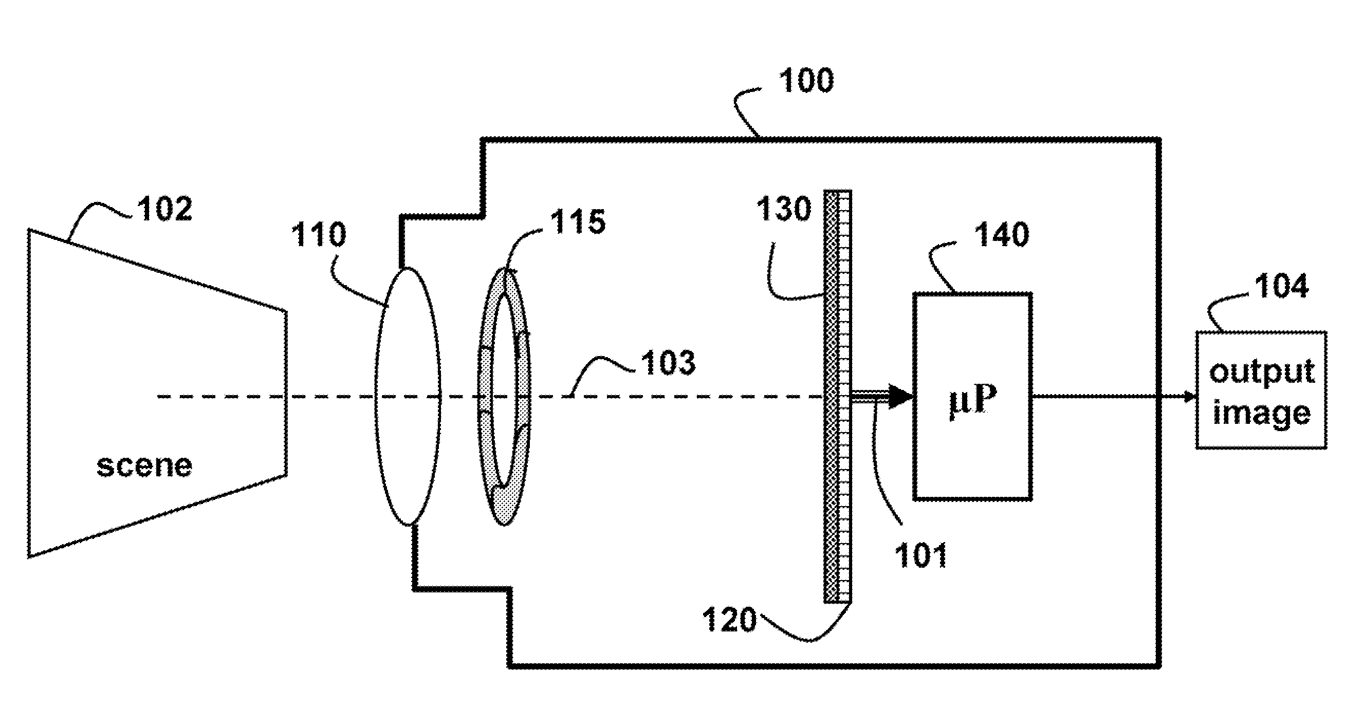
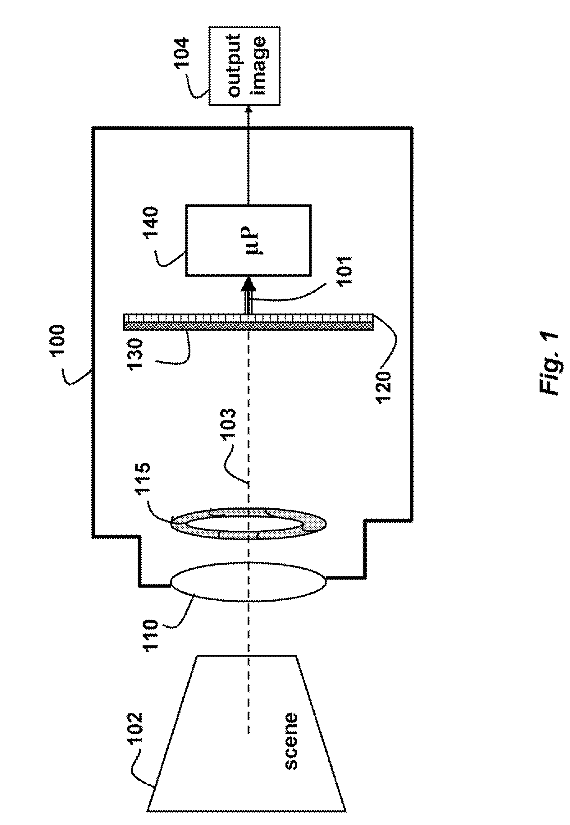
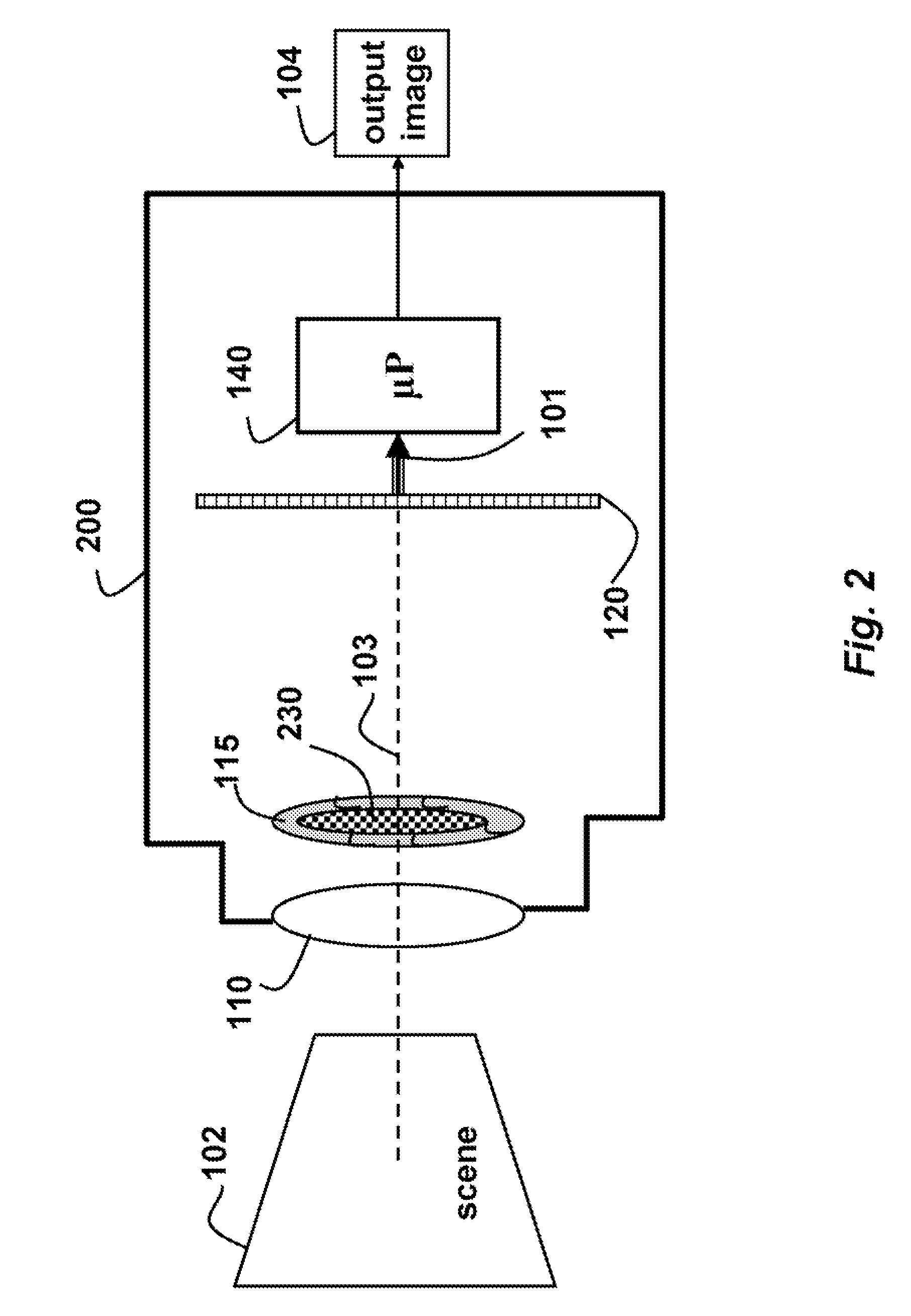
[0045]As shown in FIGS. 1 and 2, the embodiments of our invention provide cameras 100 and 200 for acquiring and reconstructing a 4D light field 101 of a scene 102. The camera 100 includes a conventional lens 110, a conventional aperture 115 and a conventional sensor 120. The lens can include multiple elements, as in a compound lens, to correct for aberrations, coma, and distortion. However, it should be understood that there is only one optical path 103. The scanner can be a CCD line-scanner.

[0046]The cameras also include a microprocessor (μP) 140 that can be used to implement the methods described herein. Basically, the microprocessor receives a 2D input image 101, which encodes the 4D light field, and can generate an output image 104, which is a reconstruction of the light field. The output image 104 is a demodulation of the input image.

[0047]Because the input image encodes the light field, the output image can be refocused at a different or greater depth ...


PUM


Abstract

A camera acquires a 4D light field of a scene. The camera includes a lens and sensor. A mask is arranged in a straight optical path between the lens and the sensor. The mask including an attenuation pattern to spatially modulate the 4D light field acquired of the scene by the sensor. The pattern has a low spatial frequency when the mask is arranged near the lens, and a high spatial frequency when the mask is arranged near the sensor.

Description

FIELD OF THE INVENTION[0001]This invention relates generally to image processing and computational photography, and more particularly to acquiring a 4D light filed of a scene with a camera.BACKGROUND OF THE INVENTION[0002]A trend in image processing and computational photography is to obtain additional optical information at the time images are acquired. This enables greater post-acquisition image processing applications, such as deblurring, refocusing, and novel images.[0003]The key idea is to acquire the entire 4D light field entering the camera, via the lens, and incident on the camera sensor. The light field is a function that describes the amount of light traveling in every direction through every point in space, Gershun, “The Light Field,” Translated by Moon et al., Journal of Mathematics and Physics, Vol. XVIII, MIT, 1939, pp. 51-151, 1939. In a conventional camera, the sensed 2D image is only a 2D projection of the 4D light field. Therefore, it is not possible to reconstruct...

Claims


Application Information

Patent Timeline
Patent Type & Authority Patents(United States)
IPC IPC(8): G03B13/00
CPCG02B27/0075
Inventor RASKAR, RAMESHAGRAWAL, AMIT KUMAR
Owner MITSUBISHI ELECTRIC RES LAB INC
Learn More