
Method and system for policy-based forwarding

a policy-based forwarding and policy-based technology, applied in the field of data communications, to achieve the effect of reducing the complexity of the overall network and the manageability problems of extra ip subnets, simple and minimal way, and improving cost-effective design

Active Publication Date: 2010-09-07
CISCO TECH INC
View PDF8 Cites 181 Cited by
  • Summary
  • Abstract
  • Description
  • Claims
  • Application Information

AI Technical Summary

Benefits of technology

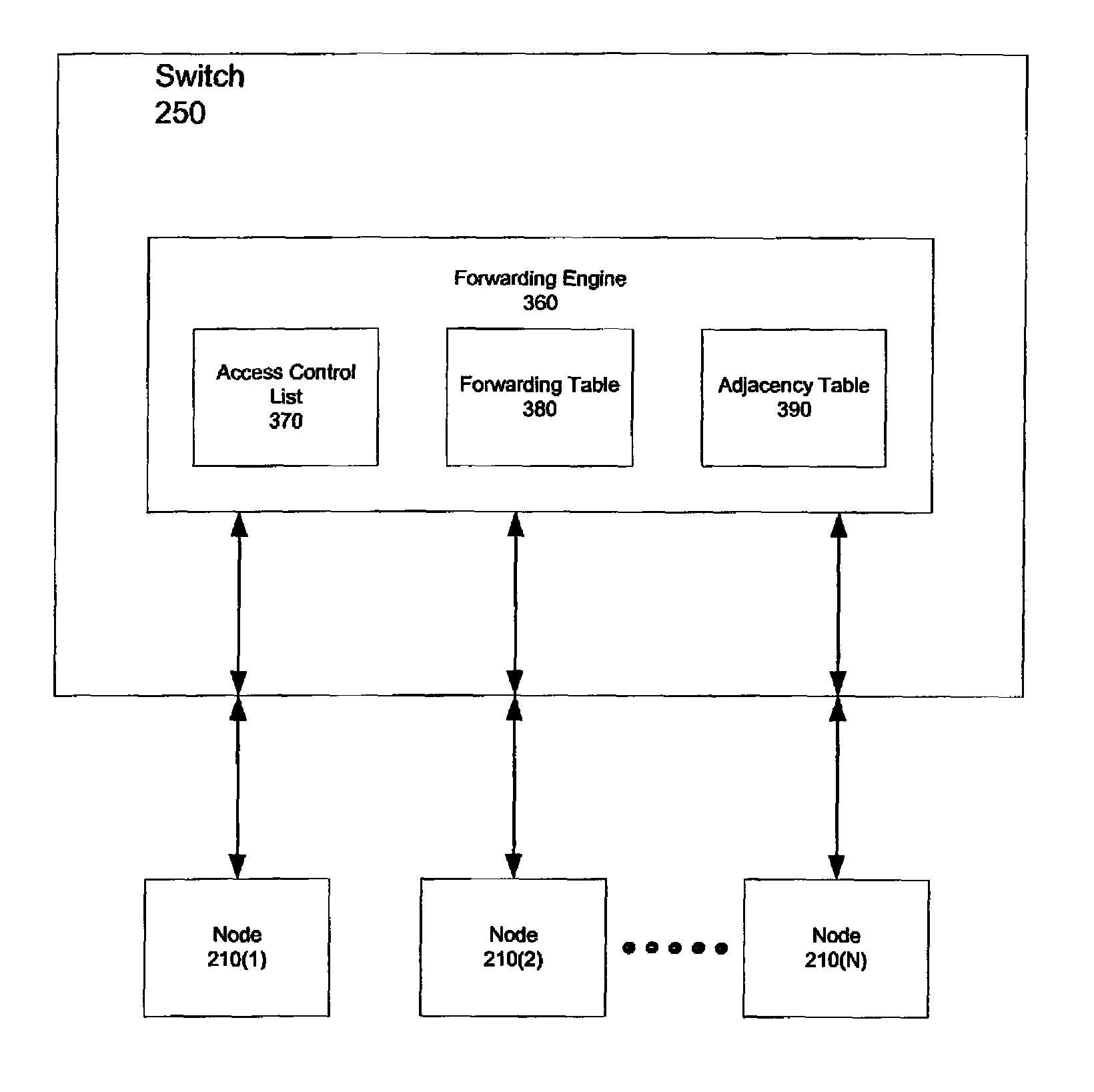
[0024]The present invention provides for policy-based forwarding (PBF) of network traffic. PBF is a feature that makes possible, for example, forwarding of network traffic between two different VLANs without having a router. This is accomplished, for example, by recognizing and re-writing a portion of a given packet, such that the packet can then be forwarded between VLANs. By changing protocol information, the altered packet can then be forwarded based on an alternative set of forwarding rules (i.e., forwarding policy). Packets can be identified individually, or as being in a certain category or group of packets. In fact, any type of filtering mechanism according to the present invention, at any network level above the given forwarding level (e.g., level-2), can be used to filter packets in this manner (for identification with regard to forwarding). Moreover, and in particular, such a PBF scheme enables a switch in a pure L2 configuration to forward traffic between VLANs based on the source and destination IP addresses. The ability to enable connectivity between devices (specifically, management devices and managed devices) across different VLAN domains in a purely L2 network is an important advantage of the present invention.
[0025]A PBF technique according to the present invention typically includes two main parts: policy configuration and adjacency configuration. The policy configuration can take advantage of existing infrastructure (e.g., commands for VACL configuration, so that filtering capabilities of VACLs can be exploited by the user for PBF purposes). In addition, such a technique provides a way to configure a “virtual” MAC address for use as a destination address for any traffic sourced in one VLAN and destined for another VLAN (or for the same one, if source and destination VLANs match). Specifically, this virtual address can be an internal address (typically the default) or a user-programmed address; the purpose of such an address is to allow the hardware forwarding engine to make forwarding decisions on packets being “handed over” by the ACL engine after being policed.
[0026]A PBF technique according to the present invention also can also be configured to provide a command line interface to configure a static adjacency data structure, namely an adjacency descriptor, containing at least the minimal amount of information required by the forwarding engine to re-write a packet. In particular, this information typically includes the following parameters: destination VLAN, destination MAC address and, optionally, source MAC address. If a well-known default gateway address is not available, then the end stations should also be configured with a static ARP entry in order for them to properly direct their traffic toward the forwarding engine for hardware switching.
[0027]In particular, an attractive advantage of a PBF technique according to the present invention is that such a technique allows a simple, minimal way of statically routing between VLANs without the need for a router and without having to configure any extra L3 interfaces / subnets. Therefore, a purely L2 transparent network can be deployed and devices can be managed from different VLANs using simple network management protocol (SNMP), without the attendant difficulties presented by additional IP address management, save for that of the devices themselves. In addition, network designs with firewall clusters and load balancers are able to seamlessly employ less expensive PBF-enabled layer-2 switches to reduce the overall network complexity and the manageability problems of extra IP subnets.
[0028]A variety of applications can find benefit in such a technique. An important advantage of a PBF technique according to the present invention is that such a technique enables policy-based inter-VLAN traffic forwarding on, for example, a pure layer-2 network without the need for routers, subnetting, configuration and maintenance of extra IP addresses or the like. Such an approach is therefore beneficial in flat, layer-2 network used for transparent bridging where extra configuration and management of subnets is undesirable, or in certain cost-sensitive applications in which a layer-2 switch can be used in lieu of a more expensive layer-3 switch to achieve a more cost-effective design, for example.
[0029]As noted, in pure layer-2 transparent networks, devices can directly communicate across VLANs if an appropriate policy (VACL) is configured on a PBF-enabled switch. So, for example, in internet data centers, such a PBF technique can be used to intercept traffic traversing a VLAN in order for that traffic to be processed by a device other than the default gateway (for instance, a load balancer). The servers in such a data center configured in this manner are not aware of the presence of this device, as the servers are configured only with the default gateway address. The PBF feature intercepts traffic based on, for example, the L3 / L4 information, and rewrites the destination MAC address to the MAC address of the L3 device with the following advantages:

Problems solved by technology

To some extent, a signal input at a second block may be conceptualized as a second signal derived from a first signal output from a first block due to physical limitations of the circuitry involved (e.g., there will inevitably be some attenuation and delay).

Method used


Image

  • Method and system for policy-based forwarding
  • Method and system for policy-based forwarding
  • Method and system for policy-based forwarding

Examples


example configuration

Operation of Example Configuration

[0063]As noted, PBF functionality is configured using, for example, Virtual Local Area Network (VLAN) Access Control Lists (ACLs) (VACLs) on the switch in question. Prior to setting the VACLs, the PBF engine should be enabled. Some configuration of the hosts is necessary: because a router is not used, the address resolution protocol (ARP) table is statically added on each host that participates in PBF scheme. To accomplish this, a packet is sent with a destination media access control (MAC) address equal to that of the “PBF engine's” MAC address.

[0064]When the packet is received, if the packet is subject to the PBF policy, the packet header is re-written (re-write of destination VLAN, source and destination MAC addresses), based on the information provided in the adjacency table, and sent to the destination VLAN. Adjacency information can also be set by the user using VACL commands. Special care should be taken because VACLs are applied to both inco...

example

[0204]Console>(debug-eng) commit security acl adjacency[0205]Commit operation in progress.[0206]Adjacency successfully committed.

Example of Setting a Switch to Provide PBF Functionality

[0207]Incoming traffic from source MAC address 00-20-20-20-20-20 . . . 00-20-20-20-20-2f is sent to destination MAC address 00-11-22-33-44-55, with source IP address 44.0.0.1 . . . 44.0.0.17 to destination IP address 43.0.0.1 . . . 43.0.0.17, and from source MAC address 00-0a-0a-0a-0a-0a . . . 00-0a-0a-0a-0a-19 to destination MAC address 00-11-22-33-44-55, with source IP address 43.0.0.1 . . . 43.0.0.17 to destination IP address 44.0.0.1 . . . 44.0.0.17. The configuration file from the switch (e.g., switch 400) deal with the first 4 cases are (44.0.0.1 . . . 44.0.0.4; 43.0.0.1 . . . 43.0.0.4):[0208]#security ACLs[0209]clear security acl all[0210]#adj set[0211]set security acl adjacency a—1 2 00-0a-0a-0a-0a-0a[0212]set security acl adjacency a—2 2 00-0a-0a-0a-0a-0b[0213]set security acl adjacency a—3 2...


PUM


Abstract

A method of operating a network is disclosed. The method includes identifying a packet as being subject to a policy and forwarding said packet based on said policy, if said packet is subject to said policy.

Description

BACKGROUND OF THE INVENTION[0001]1. Field of the Invention[0002]The present invention relates to data communications, and, more particularly, to a method and apparatus for forwarding information between network elements based on a particular forwarding policy.[0003]2. Description of the Related Art[0004]As more and more information is transferred over today's networks, businesses have come to rely heavily on their network infrastructure in providing their customers with timely service and information. While the benefits of such a network infrastructure are legion, such benefits are not without cost. Network infrastructures that are used to provide such functionality can be costly both in monetary terms and in terms of company resources expended to support such infrastructure. Moreover, a proliferation of network infrastructure involves an ever increasing need for management of the network.[0005]Thus, among the insistent requests voiced by users of such networks is a need for solutio...

Claims


Application Information

Patent Timeline
IPC IPC(8): H04L12/28H04L12/56
CPCH04L12/4675
Inventor FOSCHIANO, MARCO E.PULLELA, VENKATESHWAR R.CHEN, JUSTIN Q.BENEA, ROBERT C.PORTOLANI, MAURIZIO
Owner CISCO TECH INC
Learn More