
Battery pack

a battery pack and battery technology, applied in the field of batteries, can solve the problems of deterioration of the functionality of the thermistor, failure of electronic components on the control circuit board, and difficulty in making the battery pack sufficiently compact, so as to improve the efficiency of the assembly process contribute to the compactness of the battery pack, and improve the effect of the battery pack assembly process

Inactive Publication Date: 2010-09-07
SONY CORP
View PDF15 Cites 3 Cited by
  • Summary
  • Abstract
  • Description
  • Claims
  • Application Information

AI Technical Summary

Benefits of technology

[0012]Accordingly, it is an object of the present invention to provide a compact battery pack without sacrificing the ability to prevent an electrolyte from adhering to a control circuit-board.

Problems solved by technology

If such secondary batteries are used in an environment where the temperature and the pressure are high, for example, there may be cases where the electrolyte leaks or evaporates from the interior of the battery cell depending on the contact between the positive terminal and the battery cylinder, i.e. the outer casing of the battery cell.
This may be problematic if the electrolyte leaks or evaporates and thus adheres to the control circuit-board.
This could lead to problems, such as a short circuit in the control circuit-board, dysfunction of electronic components on the control circuit board, or an insulation failure caused by a migration of a metallic material to an insulative material.
This is problematic in that it is difficult to make the battery pack sufficiently compact.
Furthermore, since the barrier wall is integrally disposed in the casing in most cases, if the thickness of the barrier wall is reduced to achieve a compact structure for the battery pack, the fluidity of the molding resin used for fabricating the casing becomes deteriorated.
This may lead to higher manufacture costs for the battery pack since exact values may be required for the molding conditions, such as the molding temperature and injection speed.
Furthermore, since such a structure is complex due to having the barrier wall inside the casing, such a structure can lead to molding errors caused by, for example, weld marks and sink marks.
Moreover, if the battery pack receives an external impact due to, for example, dropping or vibration of the battery pack, the impact may transmit to the barrier wall and can thus cause the barrier wall to crack or break.
This is problematic in that the electrolyte may enter the control circuit-board.
Such a problem of the electrolyte entering the control circuit-board due to the cracking or breakage of the barrier wall is likely to occur especially in cases where the barrier wall is integrally disposed in the casing since the impact can easily transmit to the barrier wall.

Method used


Image

  • Battery pack
  • Battery pack
  • Battery pack

Examples


Embodiment Construction

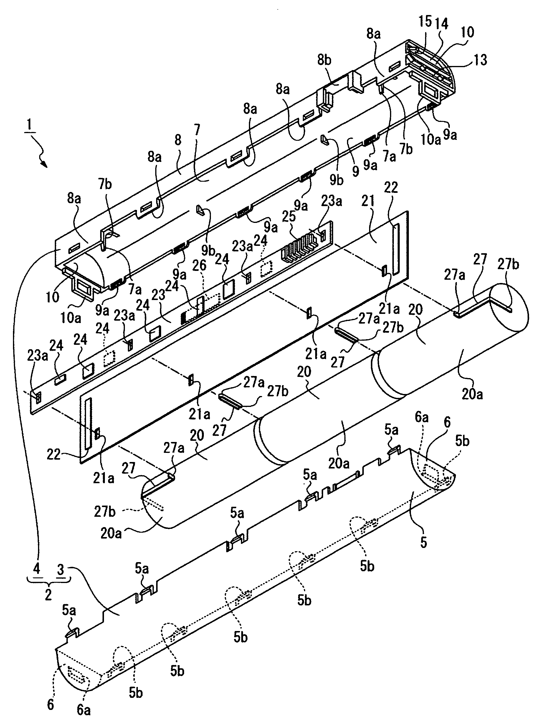
[0041]A battery pack according to the present invention will now be described with reference to the attached drawings. A battery pack according to a preferred embodiment of the present invention is used in a personal computer. However, the technical scope of the present invention is not limited to a battery pack used in a personal computer, and may include battery packs used in other types of electronic apparatuses that are driven by a battery.

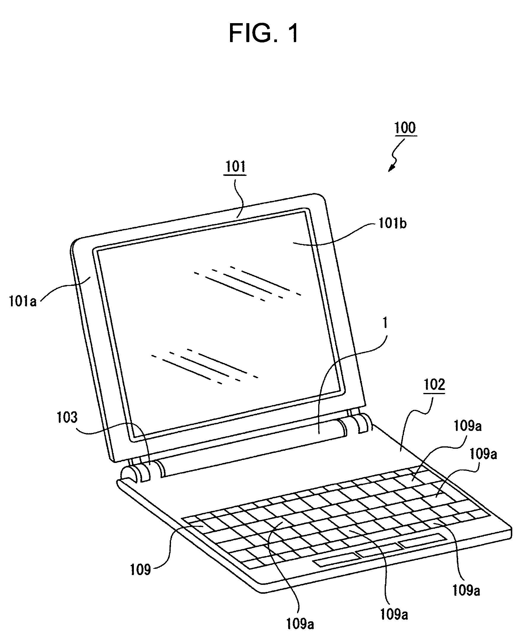
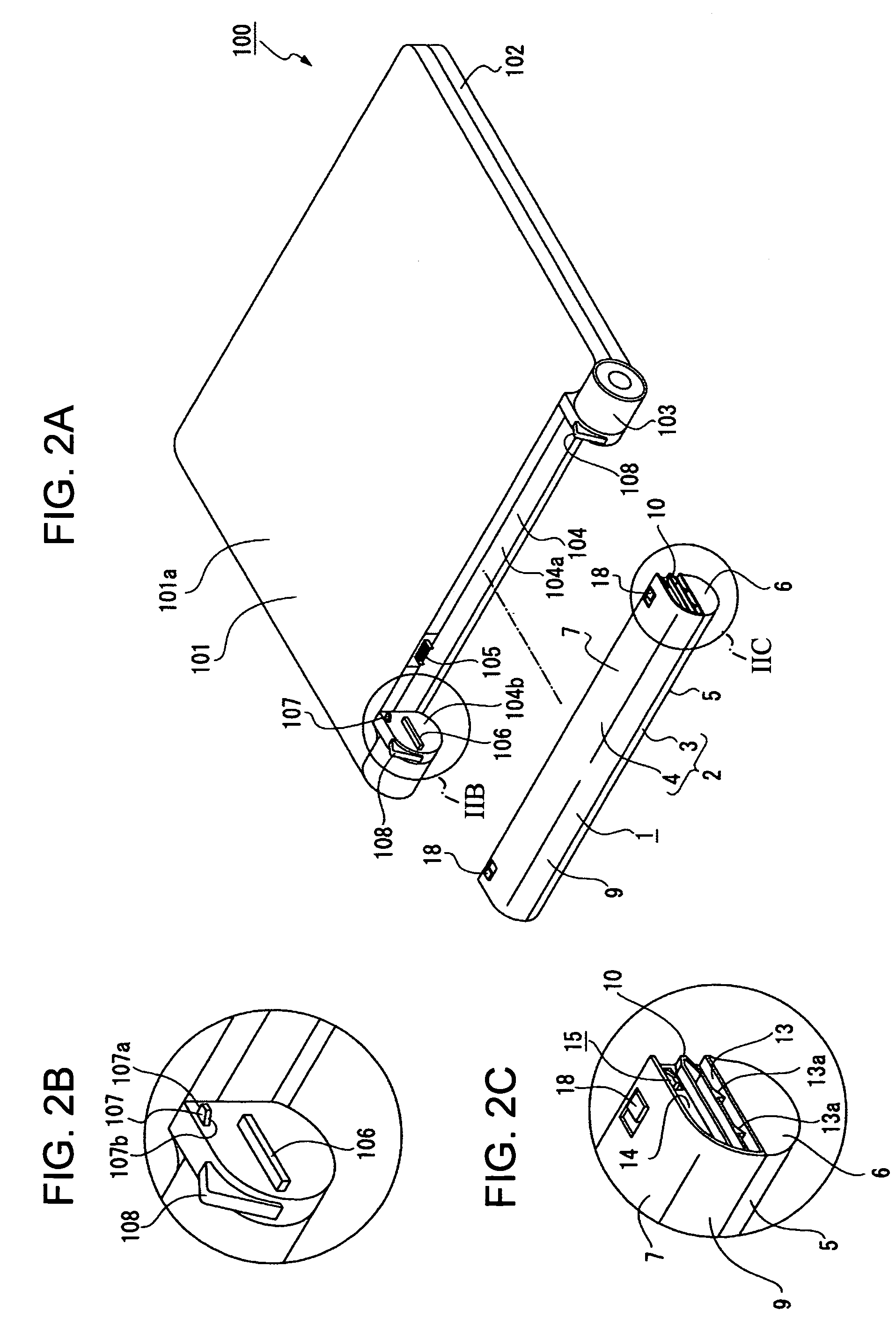
[0042]Referring to FIGS. 1, 2A, 2B, and 2C, the structure of an electronic apparatus 100, i.e. a personal computer, will first be described.

[0043]The electronic apparatus 100 includes a display unit 101 and a main-body unit 102.

[0044]The display unit 101 is provided with a display housing 101a and a display screen 101b mounted to the display housing 101a.

[0045]The display unit 101 is rotatably supported by the rear portion of the main-body unit 102 via hinges 103 provided at left and right ends of the rear portion. Here, the term “rear” will ...


PUM

PropertyMeasurementUnit
thicknessaaaaaaaaaa
surface temperatureaaaaaaaaaa
thermal-conductiveaaaaaaaaaa

Abstract

A battery pack includes a casing formed of an insulative material; a secondary battery disposed inside the casing; a control circuit-board disposed inside the casing and provided for charging and discharging the secondary battery; and a protection sheet formed of an insulative material and disposed inside the casing while being in contact with an outer surface of the secondary battery. The control circuit-board is disposed across from the secondary battery while the protection sheet is disposed therebetween. The external dimension of the protection sheet is greater than the external dimension of the control circuit-board.

Description

BACKGROUND OF THE INVENTION[0001]1. Field of the Invention[0002]The present invention relates to battery packs, and particularly, to a battery pack which is provided with a protection sheet disposed between a secondary battery and a control circuit-board, and which achieves a compact structure without sacrificing the ability to prevent an electrolyte from adhering to the control circuit-board.[0003]2. Description of the Related Art[0004]A typical battery pack is installed in a main-body unit of an electronic apparatus, such as a personal computer, and drives the battery for the main-body unit.[0005]Battery packs are generally provided with a casing in which a single secondary battery or a plurality of secondary batteries is disposed. Moreover, the casing also contains a control circuit-board for charging and discharging the secondary battery or secondary batteries. Lithium-ion batteries are widely used for the secondary batteries, and combustible organic solvents are generally used ...

Claims


Application Information

Patent Timeline
Patent Type & Authority Patents(United States)
IPC IPC(8): H01M2/14G06F1/26H01M10/00H01M10/42H01M10/46H01M50/213H01M50/264H01M50/291
CPCH01M2/1022H01M2/1094H01M10/46H01M10/425H01M10/4228Y02E60/10H01M50/24H01M50/213H01M50/264H01M50/291
Inventor OKACHI, SATOSHIWATANABE, TOMOAKI
Owner SONY CORP
Learn More