
Temperature sensor with processable front

a temperature sensor and front technology, applied in the field of temperature sensors, can solve the problems of damage to the external region of the sensor tip, adversely affecting the ability, and affecting the smooth fitting into the bor

Active Publication Date: 2010-09-07
KISTLER HLDG AG
View PDF28 Cites 332 Cited by
  • Summary
  • Abstract
  • Description
  • Claims
  • Application Information

AI Technical Summary

Benefits of technology

The present invention is about a temperature sensor with a front that can be processed. The sensor has no damage to the external part of the tip. The invention is achieved by welding each thermocouple wire to the sensor tip up to a depth that is larger than the processing depth behind the front. This results in a temperature sensor that can be easily processed without any damage to the tip.

Problems solved by technology

In particular, any unevenness, ledges or fissures towards the bores in the tools into which such sensors are inserted are reproduced on the parts, a fact which is judged as a defect.
The external region of the sensor tip, however, is damaged by the compressing during crimping which adversely affects a smooth fitting into the bore.
The damage to the external region of the sensor tip done by compressing during crimping adversely affects the ability to insert the tip into the bore of the tool as smoothly as otherwise would be possible.

Method used


Image

  • Temperature sensor with processable front
  • Temperature sensor with processable front

Examples


Embodiment Construction

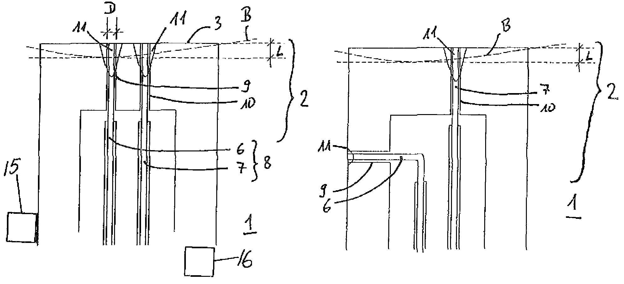
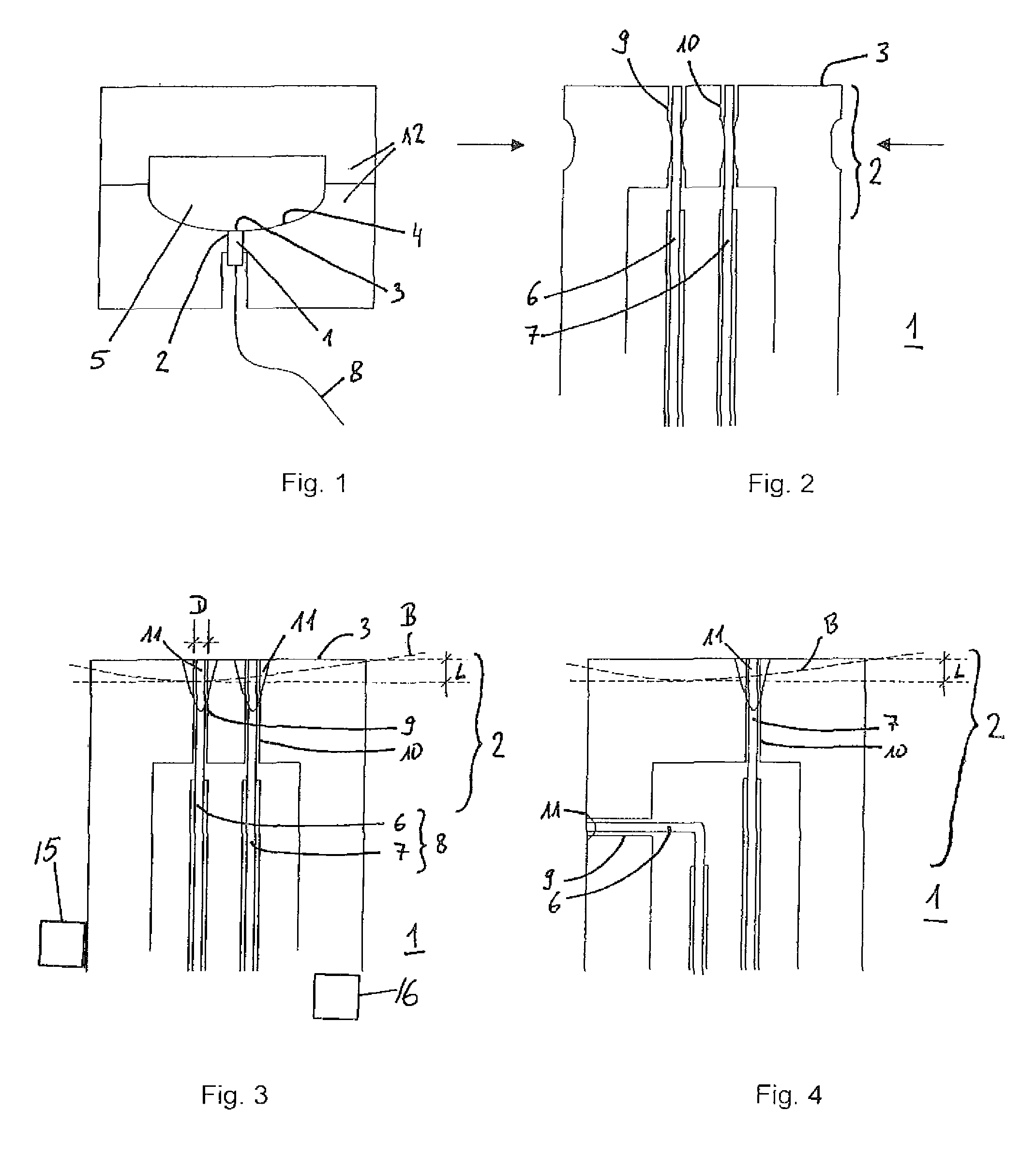
[0015]FIG. 1 shows the sensor claimed in a typical integral state. The Figure shows a schematic sectional representation of a bipartite injection molding tool 12 having a tool inner wall 4 surrounding a cavity 5. Adjacent to this tool inner wall 4 there is integrated a sensor 1 with a thermocouple 8 comprising a sensor tip 2 against the front 3 of which abuts the tool inner wall 4.

[0016]The invention describes a temperature sensor 1 having a sensor tip 2 and a front surface 3 for measuring the temperature of tool inner walls 4, particularly of injection molding tool inner walls 12, with two thermocouple wires 6, 7 of a thermocouple 8 wherein the sensor tip 2 is processable by removing of material at the front surface 3 up to a total processing depth L. The idea underlying the invention is that in the temperature sensor 1 according to the invention, each thermocouple wire 6, 7 of the thermocouple 8 guided to the front surface 3 is welded to the sensor tip 2 up to a depth which is lar...


PUM

PropertyMeasurementUnit
processing depthaaaaaaaaaa
diameteraaaaaaaaaa
processing depthaaaaaaaaaa

Abstract

A temperature sensor has a sensor tip and a front for measuring the temperature of the inner walls of tools, particularly inner walls of injection molding tools. The tip of the temperature sensor has two thermocouple wires of a thermocouple. Each thermocouple wire of the thermocouple guided to the front is welded to the sensor tip up to a depth which is larger than the total processing depth behind the front. The sensor tip is processable by removing of material at the front up to that processing depth.

Description

CROSS-REFERENCE TO RELATED APPLICATIONS[0001]This application claims priority to Swiss Application No. 01424 / 06, filed Sep. 6, 2006.TECHNICAL FIELD[0002]The invention relates to a temperature sensor having a sensor tip and a front for measuring the temperature of the inner walls of tools, particularly the inner walls of injection molding tools, wherein the sensor tip is processable by removing material at the front up to a processing depth.PRIOR ART[0003]Temperature sensors for measuring the temperature of tool inner walls of injection molding tools are known. They are used to control injection molding processes and are also available as combined pressure-temperature sensors. Usually, thermocouples are used for these applications because they have a much shorter response time compared to temperature sensors. Thermocouples are made of two thermocouple wires of different materials. In one thermocouple of the K type, for example, one of the thermocouple wires is made of nickel-chromium...

Claims


Application Information

Patent Timeline
Patent Type & Authority Patents(United States)
IPC IPC(8): G01K7/02G01K1/00
CPCB29C45/78G01K7/04
Inventor WASER, MAXPLETSCHER, ERNST
Owner KISTLER HLDG AG
Learn More