
Optical receiver reliably detectable loss-of-signal state

a technology of optical receiver and loss-of-signal state, which is applied in the field of optical receiver, can solve the problems that the conventional optical receiver does not provide a function to reliably detect the recovery of optical signals, and achieve the effects of reliably detecting the transition, reliably detecting the recovery of optical signals, and effectively detected

Active Publication Date: 2010-08-31
SUMITOMO ELECTRIC IND LTD
View PDF4 Cites 2 Cited by
  • Summary
  • Abstract
  • Description
  • Claims
  • Application Information

AI Technical Summary

Benefits of technology

The present invention provides an optical receiver with a detector that can reliably and securely detect the recovery of an optical signal from a LOS state. The detector has a bottom hold and a first comparator to detect and hold the minimum level of the output of the pre-amplifier, and a second comparator to generate an alarm when the output of the peak hold is less than a second reference. The detector also has a selector to select one of the outputs of the comparators based on the level of the alarm signal. This optical receiver can effectively detect the recovery of the optical signal from the LOS state and the change of the optical signal from the normal state to the LOS.

Problems solved by technology

Thus, the conventional optical receiver does not provide a function to reliably detect the recovery of the optical signal from the LOS state.

Method used


Image

  • Optical receiver reliably detectable loss-of-signal state
  • Optical receiver reliably detectable loss-of-signal state
  • Optical receiver reliably detectable loss-of-signal state

Examples


Embodiment Construction

[0018]Next, preferred embodiments of the present invention will be described as referring to accompanying drawings. In the description, the same numerals or symbols will refer to the same elements without overlapping explanations.

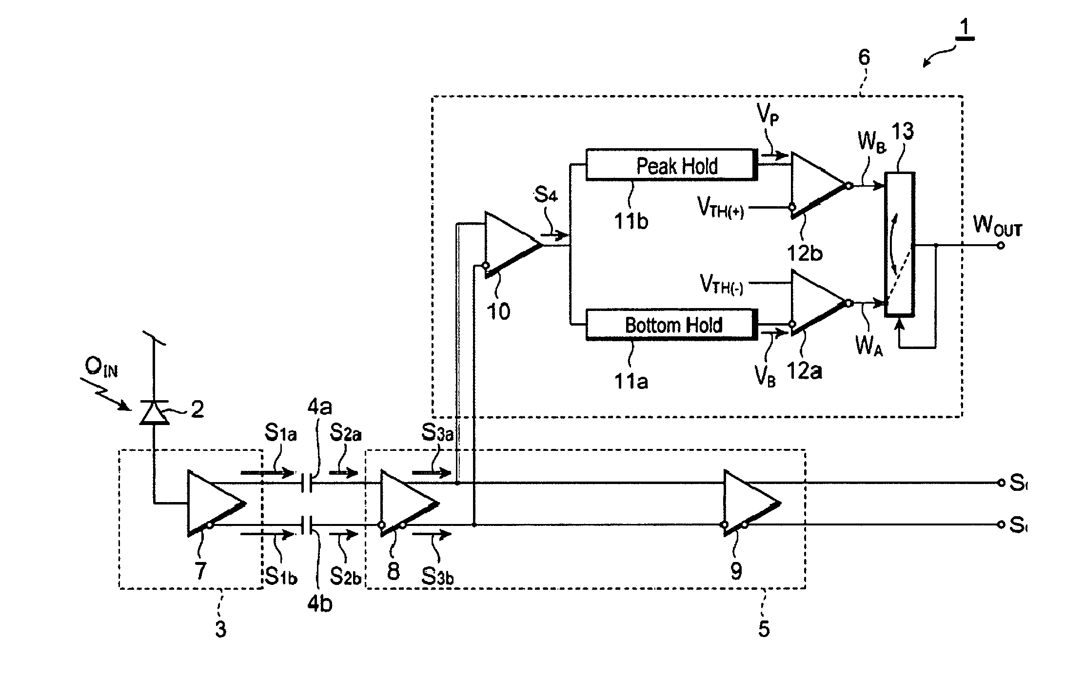
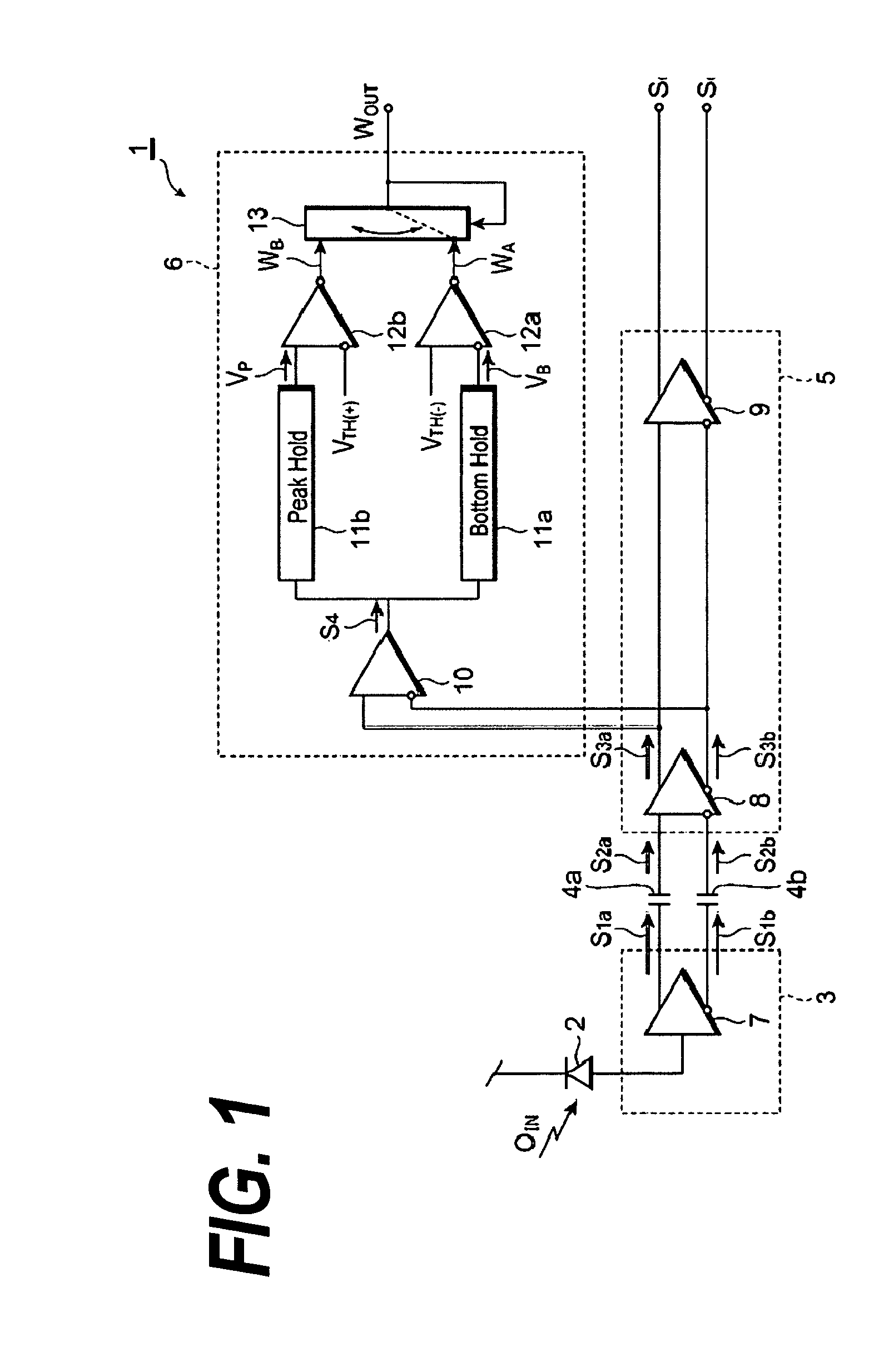
[0019]FIG. 1 is circuit diagram of an optical receiver according to one embodiment of the present invention. The optical receiver 1 shown in FIG. 1 is an apparatus to convert an optical signal OIN input from an optical fiber into an electrical signal. The optical receiver 1 comprises a light-receiving device 2 such as a semiconductor photodiode, a pre-amplifier 3, coupling capacitors, 4a and 4b, a post-amplifier 5, and a LOSS-OF-SIGNAL (LOS) detector 6. The light-receiving device 2 generates, by receiving the optical signal OIN, a photo-current depending on the intensity of the optical signal. The pre-amplifier 3 converts the photo-current output from the light-receiving device 2 into a pair of signals, S1a and S1b, with normal and reverse phases, respectiv...


PUM


Abstract

The present invention is to provide an optical receiver that prohibits the miss-detection of the recovery from the LOS (Loss-Of-Signal) state. The optical receiver includes an light-receiver device for converting an optical input signal to a photo-current, a pre-amplifier for converting this photo-current into a voltage signal, and a LOS detector to detect the LOS state based on the output from the pre-amplifier. The LOS detector includes a bottom hold that detects and keeps the bottom level of the output from the pre-amplifier and the comparator that sets the output thereof when the output from the bottom hold exceeds the threshold VTH(−).

Description

BACKGROUND OF THE INVENTION[0001]1. Field of the Invention[0002]The present invention relates to an optical receiver applicable in the optical communication.[0003]2. Related Prior Art[0004]A SFP (Small Form-Factor Pluggable) link has been widely spreading as one type of optical transceivers. For instance, a home page on the internet, “INF-8074 specification for SFP (Small Form Factor Pluggable Transceiver Rev. 1.0”, May 12, 2001; ftp: / / ftp.seagate / com / sff / ING-8074.pdf; by the SFF committee, has disclosed a specification of such a transceiver.[0005]The SFP transceiver is requested to have a function that, when the optical input signal becomes less than intensity specified by the standard due to the breakdown or the miss connecting of the optical fiber, or due to the failure of the optical transmitter, the transceiver sets a LOS (Loss Of Signal) alarm. In addition to the function mentioned above, the optical transceiver is necessary to reset the LOS alarm when the optical input signal...

Claims


Application Information

Patent Timeline
Patent Type & Authority Patents(United States)
IPC IPC(8): H04B10/06H01S3/00H04B10/40H04B10/07H04B10/50H04B10/60
CPCH04B10/077H04B10/07955H04B10/66
Inventor MURAYAMA, TETSU
Owner SUMITOMO ELECTRIC IND LTD
Learn More