
Clamp for interconnecting orthogonally oriented pipes

a technology of orthogonal orientated pipes and clamps, which is applied in the field of clamps, can solve the problems of increasing requiring special tools and/or skilled labor, and requiring relatively complex and costly clamping devices, etc., and achieves the effects of simple and low cost clamps, and reducing the likelihood of livestock injury

Active Publication Date: 2010-08-31
BECKER RENAE E
View PDF19 Cites 17 Cited by
  • Summary
  • Abstract
  • Description
  • Claims
  • Application Information

AI Technical Summary

Benefits of technology

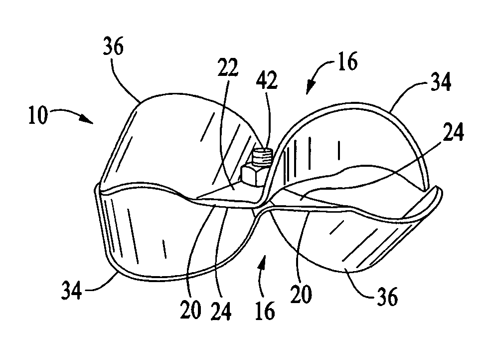
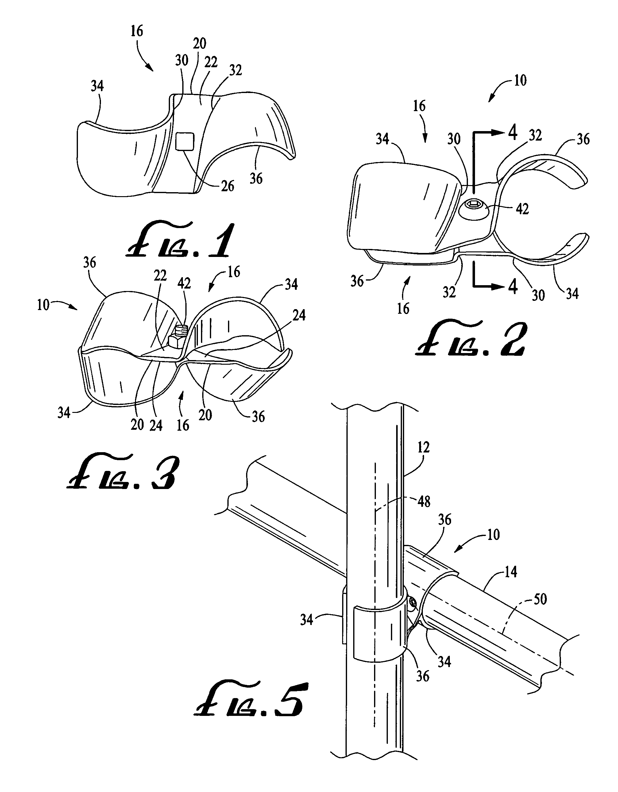
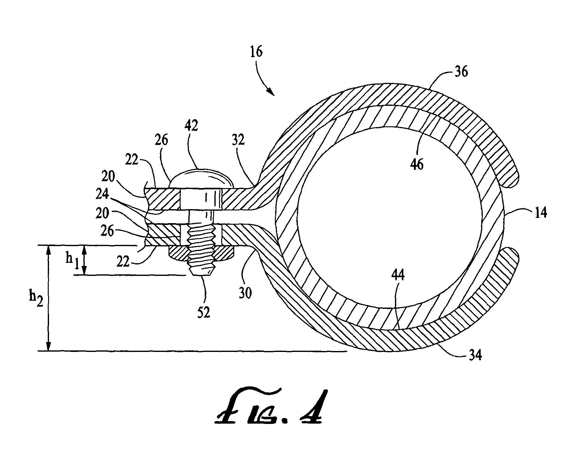
"The present invention provides simple and low-cost clamps for securely interconnecting pairs of crossing pipes using a single fastener. The clamps can be used to connect pipes in the same plane or at different orientations. The clamps have curved jaws that grip the pipes tightly, and the fastener passes through the aligned apertures in the clamps. The clamps can be easily assembled and disassembled with ordinary tools and without skilled labor. The clamps are designed to prevent injury to livestock or personnel and can be used for fencing or livestock enclosures. The invention provides a solution for quickly assembling and disassembling any built-up pipe structure that has orthogonally crossed pipes."

Problems solved by technology

Also, clamping devices for interconnecting pipes at right angles relative to each other are available but tend to be relatively complex and costly.
Still other, known pipe interconnection devices require special tools and / or skilled labor such as welders.

Method used


Image

  • Clamp for interconnecting orthogonally oriented pipes
  • Clamp for interconnecting orthogonally oriented pipes
  • Clamp for interconnecting orthogonally oriented pipes

Examples


Embodiment Construction

[0017]The following description is of a first mode presently contemplated for practicing the invention. This description is not to be taken in a limiting sense but is made merely for the purpose of describing the general principles of the invention whose scope may be ascertained by referring to the appended claims.

[0018]The terms “pipe” and “pipes” are used herein in a comprehensive sense, being intended to include, without limitation, posts (typically vertically oriented), rails (typically running transversely or horizontally), tubes, and other pipe-like members that in various assembled structures such as fences and livestock enclosures often cross over or are otherwise disposed at right angles relative to each other.

[0019]The interconnected pipes may form part of a frame or panel that may, in turn, comprise part of a fence such as a chain link fence or a livestock enclosure such as a horse corral in which vertical posts are interconnected with transverse or horizontal rails where...


PUM


Abstract

A clamp for connecting a pair of orthogonally disposed pipes. The clamp may comprise a pair of identical clamp halves or brackets, or a pair of mirror-image clamp halves or brackets, each bracket having a centrally located plate portion having one or more apertures, an upper surface, a lower surface and spaced apart ends, each of the ends carrying a curved jaw designed to conform to cylindrical outer surfaces of the pipes. The lower surfaces of the plate portions of the pair of clamp brackets are disposed in confronting relationship with their apertures in alignment, the pair of brackets being coupled with one or more fasteners passing through the aligned apertures. The end jaws of one of the brackets are in opposed relationship with the corresponding end jaws of the other of the brackets, wherein the end jaws of the coupled brackets define a pair of generally cylindrical pipe gripping surfaces each having a longitudinal central axis. The orientation of the jaws relative to their respective plate portions is such that the longitudinal central axis of one of the pair of generally cylindrical pipe gripping surfaces is orthogonal to the longitudinal central axis of the other of the pair of generally cylindrical pipe gripping surfaces.

Description

FIELD OF THE INVENTION[0001]This invention relates generally to clamps and particularly to a clamp for coupling a pair of orthogonally oriented pipes such as may be found in fencing such as a livestock corral or other enclosure.BACKGROUND OF THE INVENTION[0002]Existing pipe frame or panel structures for fencing, livestock enclosures and the like often incorporate clamping devices for interconnecting two pipes that are disposed parallel to each. Also, clamping devices for interconnecting pipes at right angles relative to each other are available but tend to be relatively complex and costly. Still other, known pipe interconnection devices require special tools and / or skilled labor such as welders.SUMMARY OF THE INVENTION[0003]The present invention provides simple, low cost clamps for securely interconnecting a pair of crossing pipes, usually of equal diameters, using a single, commercially available fastener. A first embodiment is intended to clamp orthogonal pipes in the same plane, ...

Claims


Application Information

Patent Timeline
Patent Type & Authority Patents(United States)
IPC IPC(8): F16L3/22
CPCF16L3/02F16L3/085F16L3/2235F16L3/237E04H17/1473
Inventor BECKER, RENAE E.
Owner BECKER RENAE E
Learn More