
Golf ball and die for molding the same

a golf ball and die technology, applied in the field of golf balls and dies for molding golf balls, can solve the problems of not disappearing, and achieve the effects of improving the workability of grinding quantity measurement, ensuring accuracy, and ensuring accuracy

Inactive Publication Date: 2010-08-24
BRIDGESTONE SPORTS
View PDF12 Cites 2 Cited by
  • Summary
  • Abstract
  • Description
  • Claims
  • Application Information

AI Technical Summary

Benefits of technology

The present invention provides a golf ball with controlled depths of dimples after grinding, which affects the trajectory of the ball. This is achieved by a golf ball molding die with a protrusion on the cavity side surface, which is high enough to prevent the depression on the surface of the ball from disappearing during grinding. The protrusion is positioned in a specific range and has a uniform height from the surface. The invention also provides a golf ball with stable and easy flight along a proper trajectory.

Problems solved by technology

The protrusion can be high enough that the depression formed on the surface of golf ball by the protrusion does not disappear by properly grinding the surface of golf ball.

Method used


Image

  • Golf ball and die for molding the same
  • Golf ball and die for molding the same
  • Golf ball and die for molding the same

Examples


Embodiment Construction

[0021]One embodiment of the present invention will now be described with reference to the accompanying drawings. As a specific example, a case is explained in which a two-piece solid golf ball is manufactured by molding a cover layer around a rubber-made elastic body, which is a core material, by injection molding. The present invention is not limited to this embodiment, and can be applied to other types of gall balls.

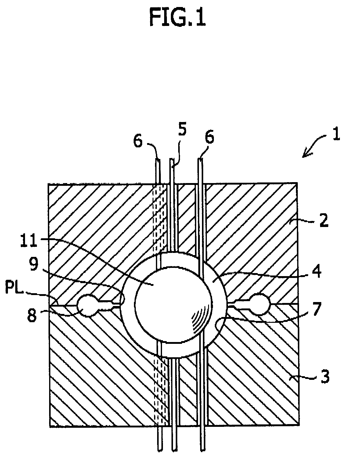
[0022]As shown in FIG. 1, when the golf ball is manufactured by the injection molding, an injection molding die 1 is used. This injection molding die 1 includes an upper die 2 and a lower die 3, which are made of a metal. By separably joining the upper die 2 and the lower die 3 to each other, a spherical cavity 4 is formed in the die 1.

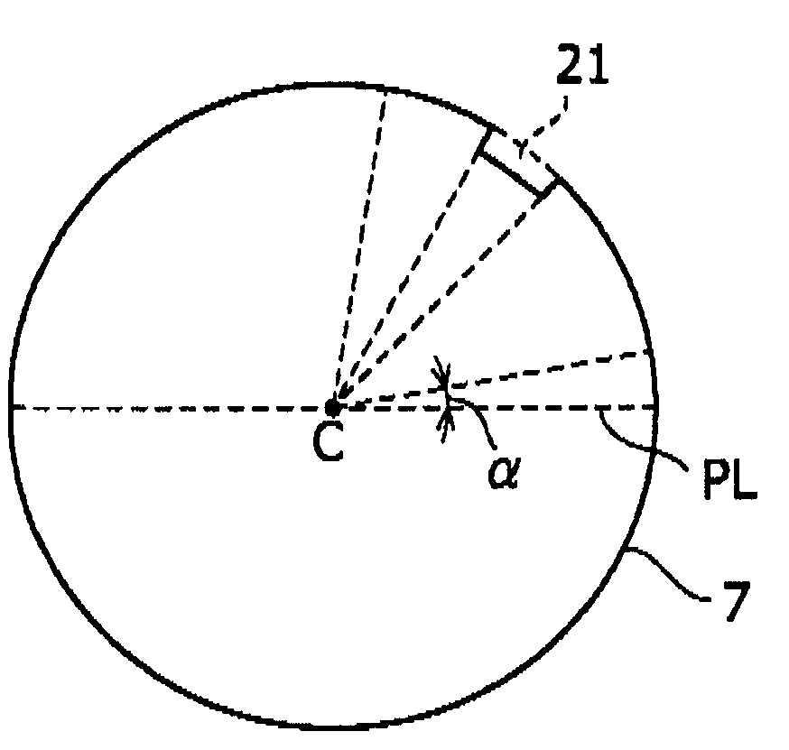
[0023]A parting line PL of the upper die 2 and the lower die 3 is located at a position corresponding to the equator, that is, latitude zero degree of the cavity. On the cavity wall surface 7 of the molding die 1, a large number of conve...


PUM

PropertyMeasurementUnit
latitudeaaaaaaaaaa
latitudeaaaaaaaaaa
latitudeaaaaaaaaaa

Abstract

There are provided a golf ball in which the depths of dimples after grinding, which greatly affect the trajectory of golf ball, can be controlled readily and exactly, and a golf ball molding die for manufacturing the golf ball. The golf ball molding die in accordance with the present invention comprises two die bodies in which a cavity for molding a golf ball is formed by joining the die bodies to each other; and a protrusion formed on the cavity side surface of at least one of the die bodies, the protrusion having a uniform height from the surface or an imaginary spherical surface on which the protrusion is assumed to be absent toward the center of the cavity, wherein when a parting line is at latitude zero degree, the protrusion is arranged in the range of from latitude about 10 degrees to latitude about 80 degrees.

Description

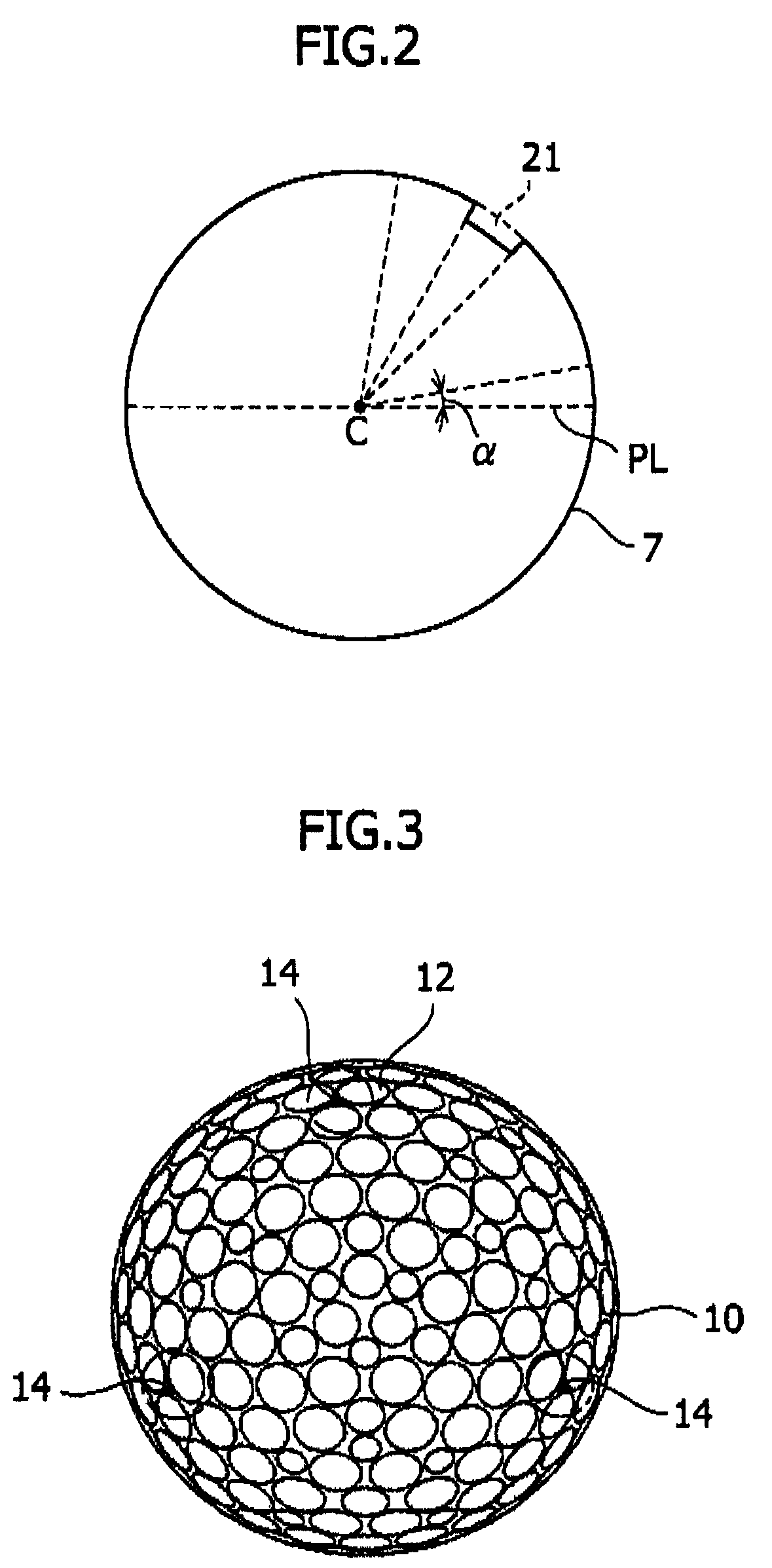
BACKGROUND OF THE INVENTION[0001]The present invention relates to a golf ball and a die for molding the golf ball.[0002]A golf ball is usually manufactured by coating a core material thereof with a cover layer by using a die. This die is provided with support pins and vent pins. Also, the die includes an upper die and a lower die, which are joined to each other at a parting line. The support pins, vent pins, and parting line produce burrs on the surface of golf ball. The burrs must be removed by grinding, because they may greatly impair the aerodynamic characteristics of golf ball.[0003]If the surface of golf ball, i.e., the surface of cover layer is ground for removing burrs, the dimples formed on the surface of cover layer each must have a specified depth. Therefore, the depths of dimples are measured repeatedly so that the dimples each have a specified depth while the surface of cover layer is ground.[0004]The depth of dimple is usually measured by using a depth micrometer or sim...

Claims


Application Information

Patent Timeline
Patent Type & Authority Patents(United States)
IPC IPC(8): B29C45/14
CPCA63B37/0004A63B45/00B29C37/02A63B45/02B29C33/424B29C45/14819B29L2031/54B29L2031/545A63B37/0019A63B37/0074
Inventor SATO, KATSUNORIMITAMURA, ATSUSHI
Owner BRIDGESTONE SPORTS
Learn More