
Integrated gate drive for use in control and protection of power modules

a gate driver and integrated technology, applied in relays, pulse techniques, transportation and packaging, etc., can solve the problems of increasing the cost of each unit, affecting the safety of power modules, so as to achieve safe, reliable and cost-effective effects

Inactive Publication Date: 2010-08-17
HONEYWELL INT INC
View PDF10 Cites 12 Cited by
  • Summary
  • Abstract
  • Description
  • Claims
  • Application Information

AI Technical Summary

Benefits of technology

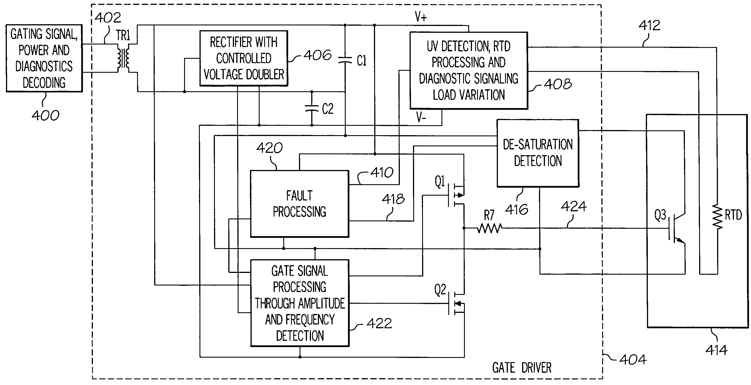
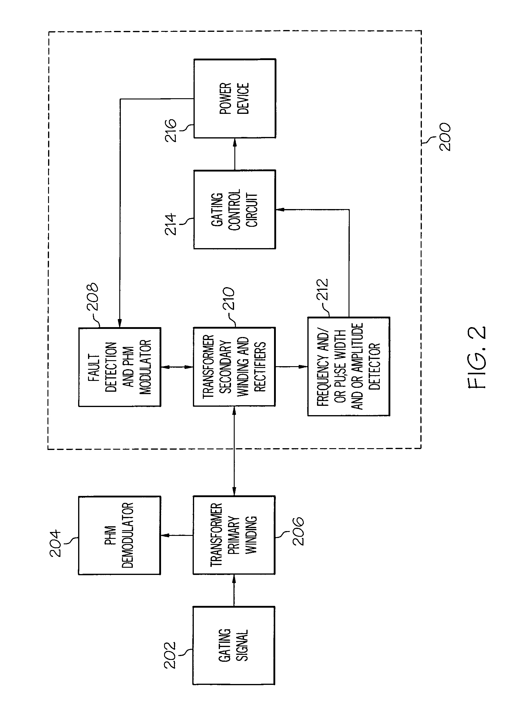
The present invention is about safely and reliably interfacing a gating signal with a high Power Device using a single transformer primary winding block and a physically isolated Gate Driver unit. This invention provides a cost-effective solution for high Power Devices that require a reliable and safe interface with a gating signal. The technical effects of this invention include improved safety, reliability, and cost-effectiveness for high Power Devices that require a reliable and safe interface with a gating signal.

Problems solved by technology

HPSMs, with or without Integrated Gate Drivers, are frequently used in a variety of terrestrial and non-terrestrial operating conditions and are subject to degradation and failure from atmospheric and non-atmospheric contaminants.
The process of sealing an HPSM is difficult and expensive, requiring all pin connections into and out of the HPSM to be prepared and sealed prior to use.
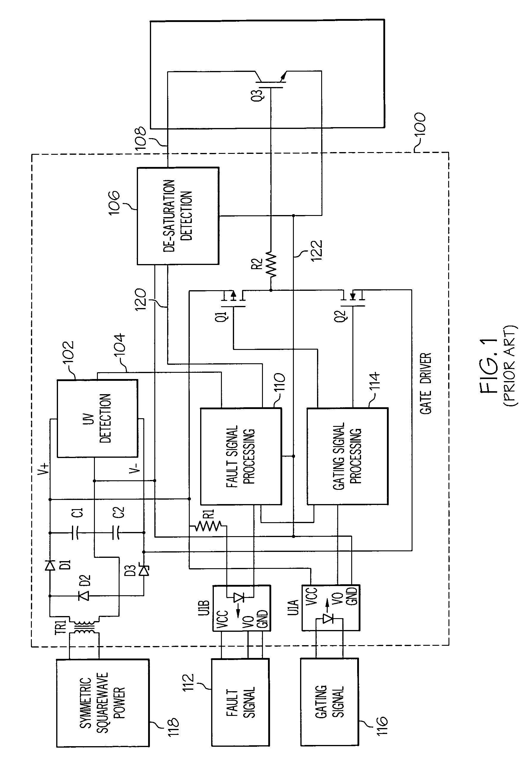
As shown in the TD350 brochure and in U.S. Pat. No. 6,851,077, typical Gate Drivers have multiple connections both into and out of the module, thereby sealing each unit before putting a unit into operation makes each unit more expensive.
Moreover, hermetically sealing each unit to keep out humidity or for use under reduced atmospheric pressure or in a vacuum, such as outer space, is significantly more difficult and expensive.
However, the '432 patent does not show how V− for turn off is derived nor does it propose or discuss how to realize a hermetic Gate Driver plus Power Device.
In general, implementation of such features typically requires additional components, additional pin connections and increased board space, thus adding to cost and weight and potential unreliability of the Gate Driver.
Moreover, any additional I / O pin connections make the unit correspondingly difficult and expensive to seal.
As one can easily understand, an application environment requiring a hermetically sealed unit having onboard diagnostics makes the cost to hermetically sealing the unit significant.

Method used


Image

  • Integrated gate drive for use in control and protection of power modules
  • Integrated gate drive for use in control and protection of power modules
  • Integrated gate drive for use in control and protection of power modules

Examples


Embodiment Construction

[0030]The following detailed description is of the best currently contemplated modes of carrying out the invention. The description is not to be taken in a limiting sense, but is made merely for the purpose of illustrating the general principles of the invention, since the scope of the invention is best defined by the appended claims.

[0031]In high power electronic applications, the Gate Driver needs to be installed very close (in most cases, direct-mount at Power Device control-pins) to the Power Devices. This very close proximity is required to avoid degradation of gating signals due to parasitic inductances and / or prevent noise / delay to gating patterns.

[0032]The present invention presents the concept of integrating the Gate Driver in a hermetic package, which not only puts the Gate Driver right on the device, but also protects the Gate Driver from harsh environmental conditions such as extreme high / low temperatures, and provides protection against condensation and contamination. O...


PUM


Abstract

A method and apparatus for providing isolated high and low direct current power supplies to a Power Device using a sealed high Power Device Gate Driver having a single transformer, wherein the Gate Driver integrates the power supplies, gating control and gate control, gate drive and Power Device diagnostics into a sealed unit, wherein the unit may be further sealed hermetically.

Description

CROSS REFERENCE TO RELATED APPLICATIONS[0001]This present application claims benefit of U.S. Provisional Patent Application Ser. No. 60 / 915,812 filed May 3, 2007, which is incorporated herein by reference in its entirety and for all purposes.BACKGROUND OF THE INVENTION[0002]The present invention relates generally to a magnetically coupled Gate Driver for providing transformer isolated high and low control and gate drive to Power Devices, such as IGBT or MOSFET, using a single transformer and no interface opto-couplers for the Gating or Fault signals. More particularly, the Gate Driver of the present invention may be hermetically sealed and integrates high and low direct current power supplies, gating control, gate drive and Power Device diagnostics into a sealed Integrated Power Device Package. This eliminates the need for opto-coupler or I / O (input / output) pin connections or wires through the wall of the device package which would increase the complexity and cost of achieving a her...

Claims


Application Information

Patent Timeline
Patent Type & Authority Patents(United States)
IPC IPC(8): H01H35/00
CPCH02M1/08H03K17/0406H03K17/18H03K17/567H03K17/0412H03K17/168H03K17/22H03K17/691H03K2017/0806H03K17/78H03K2217/0081
Inventor KOJORI, HASSAN ALIPATON, ROBERT D.EFTYCHIOU, ANDREW
Owner HONEYWELL INT INC
Learn More