
Drive mechanism

a technology of drive mechanism and drive shaft, which is applied in the direction of movable seats, gearing, roofs, etc., can solve the problems of increasing the cost of seat track assembly, and affecting the safety of passengers,

Inactive Publication Date: 2010-08-17
SCHUKRA OF NORTH AMERICA
View PDF227 Cites 14 Cited by
  • Summary
  • Abstract
  • Description
  • Claims
  • Application Information

AI Technical Summary

Benefits of technology

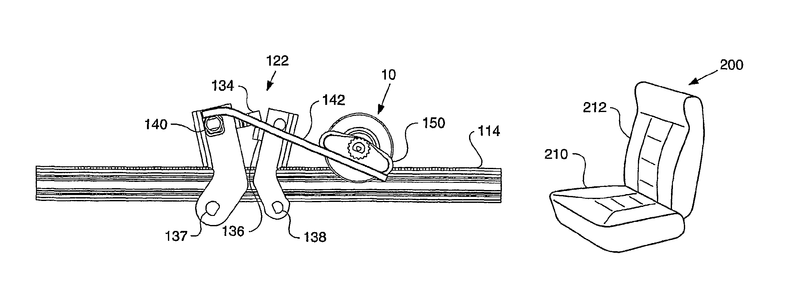
[0012]In a second example, the hollow axle motor assembly forms part of the seat hinge. In other words, the hollow axle motor assembly is coaxial with the seat hinge. In this manner, the hollow axle motor assembly can be engaged to adjust the inclination of the seat back. This provides a compact arrangement for electrically adjusting the inclination of the seat back.

Problems solved by technology

These devices are somewhat complex.
This often involves a complex, inefficient, and expensive arrangement of stops and limit switches.
While the separate locking mechanism contributes to crash worthiness of the seat track assembly, the complex arrangement of the stops and limit switches significantly adds to the cost of the seat track assembly.
Moreover, having two separate actuators significantly adds to the weight of the seat track assembly.
This results in a bulky package.

Method used


Image

  • Drive mechanism
  • Drive mechanism
  • Drive mechanism

Examples


Embodiment Construction

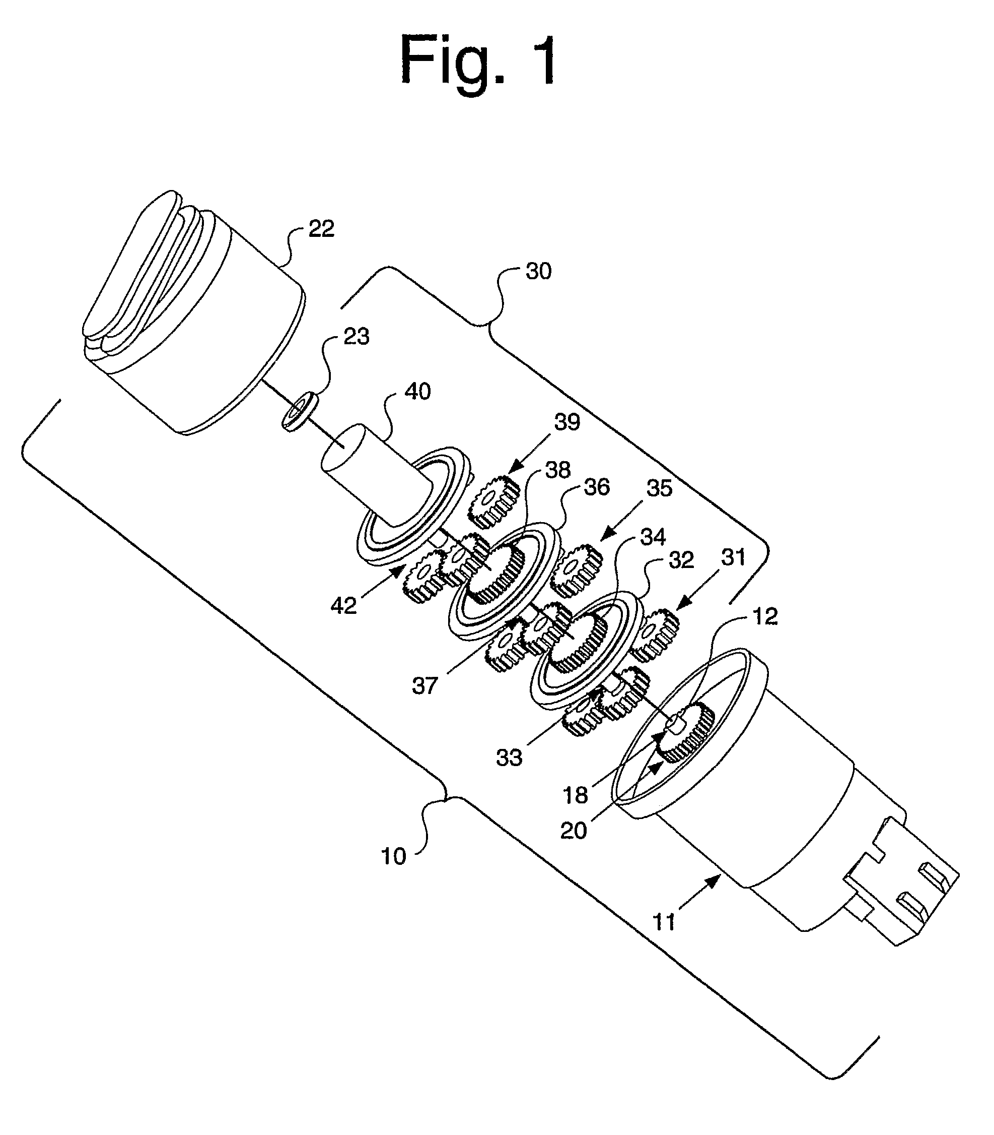
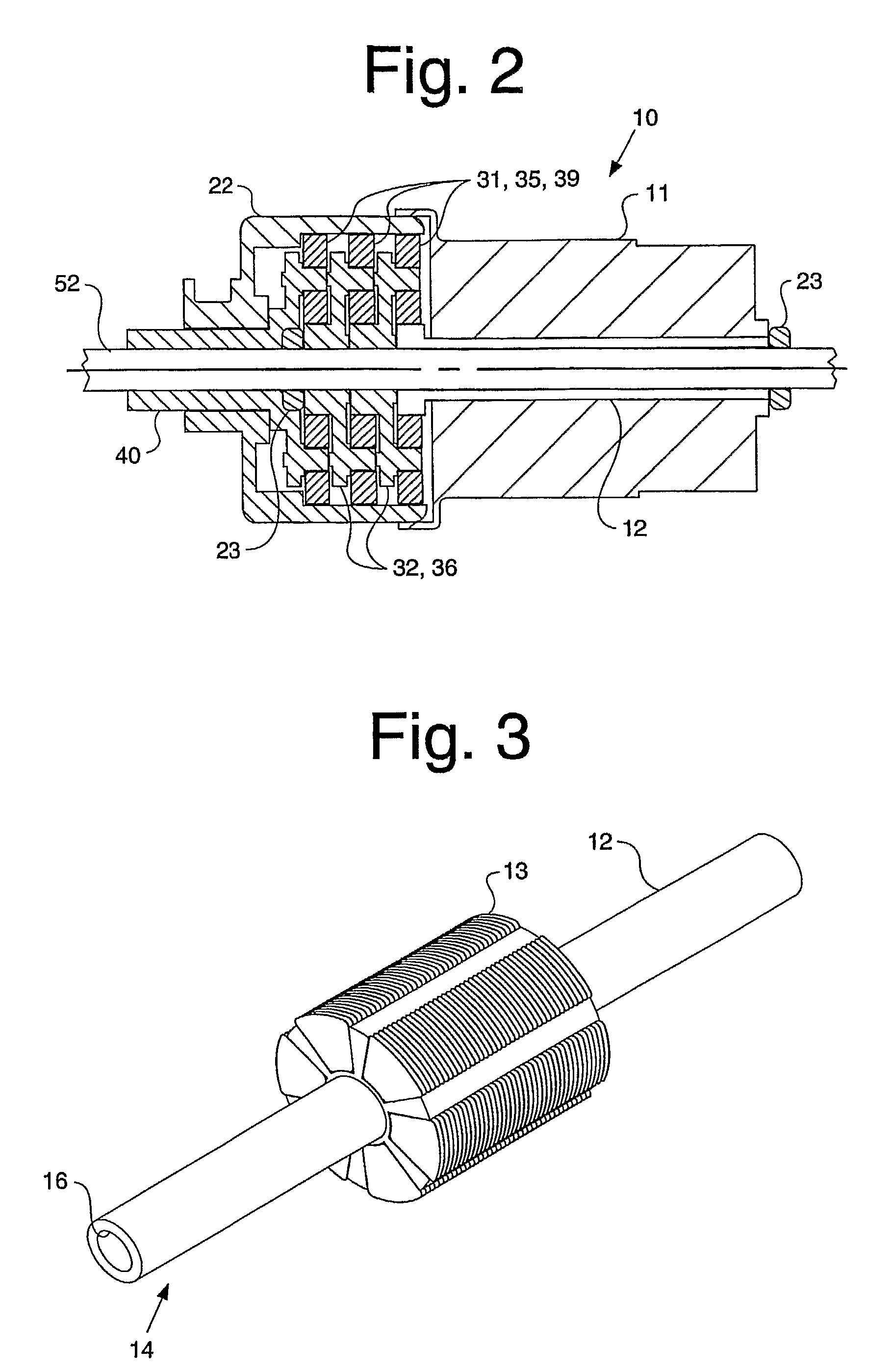
[0030]Referring to the accompanying drawings in which like reference numbers indicate like elements, FIGS. 1 and 2 illustrate a hollow axle motor assembly 10. The hollow axle motor assembly 10 includes a motor 11. The motor 11 includes a hollow axle 12. As best seen in FIG. 3, the hollow axle 12 is connected to an armature 13 of the motor 11. The hollow axle 12 includes an outer diameter 14 and an inner diameter 16. Returning once again to FIG. 1, a first gear 20 is connected to the hollow axle 12. In the depicted embodiment, the first gear 20 is connected to an end portion 18 of the hollow axle 12, and the first gear 20 is the sun gear of a planetary gear set. While in the depicted embodiments a planetary gear set is shown, it is within the scope of the present invention that other types of gear sets may be used to engage the hollow axle 12.

[0031]The first gear 20 is in driving communication with a planetary gear drive assembly 30. In the depicted embodiment, the planetary gear dri...


PUM


Abstract

A hollow axle motor assembly (10) includes an armature (13) and a hollow axle (12) attached to the armature (13). The hollow axle (12) has an outer diameter (14) and an inner diameter (16). The inner diameter (16) of the hollow axle (12) receives a shaft or tube, such as a drive shaft (52). A gear (20) is attached to the outer diameter (14) of the hollow axle (12). The gear (20) is in driving communication with a planetary gear drive assembly (30). In turn, the planetary gear drive assembly (30) is in driving communication with a drive shaft mount (40). The drive shaft mount (40) can be used to drive any number of conventional items, including, for example, the drive shaft (52).

Description

CROSS-REFERENCE TO RELATED APPLICATIONS[0001]This application claims priority of U.S. Provisional Application No. 60 / 542,343 filed on Feb. 6, 2004.BACKGROUND OF THE INVENTION[0002]1. Field of the Invention[0003]This invention relates generally to drive mechanisms and, more particularly, to a hollow axle motor assembly.[0004]2. Related Art[0005]Electric motor drive arrangements for seat movement and ergonomic support movement are known. Typically, the motor has a shaft and a gear drive arrangement is attached to the shaft. In the known devices, output from the motor / gear drive arrangement has only been available on one end of the motor. For some time, there has been a need for a dual output motor and planetary gear drive arrangement. Such a device could provide a compact and cost-effective package to drive any number of seat mechanisms. There remains a need in the art for a compact and cost-effective combination motor and gear drive arrangement having dual output.[0006]Seat track ass...

Claims


Application Information

Patent Timeline
Patent Type & Authority Patents(United States)
IPC IPC(8): B60N2/02F16M13/00B60N2/06B60N2/08B60N2/225F16H1/28F16H1/46
CPCB60N2/0232B60N2/067B60N2/0818B60N2/0825B60N2/0881F16H1/46B60N2/085Y10T74/20341B60N2002/0236B60N2/02253B60N2/02246
Inventor MCMILLEN, ROBERT J.KOPETZKY, ROBERTBENSON, JOSEPHKOGEL, HANSBLENDEA, HORIA
Owner SCHUKRA OF NORTH AMERICA
Learn More