Heat exchanger header tank and heat exchanger comprising same

a heat exchanger and header technology, applied in indirect heat exchangers, refrigeration components, lighting and heating apparatus, etc., can solve the problems of cumbersome procedure for partitioning, low efficiency of work for joining the caps, and increasing the number of components, so as to reduce the number of working steps, shorten the working time, and improve heat exchange efficiency

Inactive Publication Date: 2010-08-17
RESONAC HOLDINGS CORPORATION
View PDF11 Cites 7 Cited by
  • Summary
  • Abstract
  • Description
  • Claims
  • Application Information

AI Technical Summary

Benefits of technology

[0031]With the heat exchanger header tank according to par. 1), the header forming plate has an outward bulging portion extending longitudinally thereof and having an opening closed with the intermediate plate. This eliminates the need to use caps for closing opposite end openings unlike the header tank of the above-mentioned publication. As a result, the components can be smaller in number, while the work for joining the caps becomes unnecessary, further obviating the work for making the caps as separate members.
[0045]The heat exchanger according to par. 16) enables the refrigerant to flow favorably to achieve an improved heat exchange efficiency. For example, when used as an evaporator for supercritical refrigerant cycles, the heat exchanger exhibits improved heat exchange performance.

Problems solved by technology

However, the header tank included in the heat exchanger of the publication requires caps for closing opposite end openings and therefore has the problem of necessitating an increased number of components and being low in the efficiency of work for joining the caps to the header member, pipe connecting plate and intermediate plate.
Additionally, the caps must be made as separate members and are cumbersome to make.
To improve the heat exchanger disclosed in the publication in heat exchange performance, it is desirable to change the course of flow of the refrigerant, for example, by dividing the interior of at least one of the header tanks with a partition, whereas this entails the problem that the provision of the partition requires a cumbersome procedure.

Method used


Image

  • Heat exchanger header tank and heat exchanger comprising same
  • Heat exchanger header tank and heat exchanger comprising same
  • Heat exchanger header tank and heat exchanger comprising same

Examples


embodiment 1

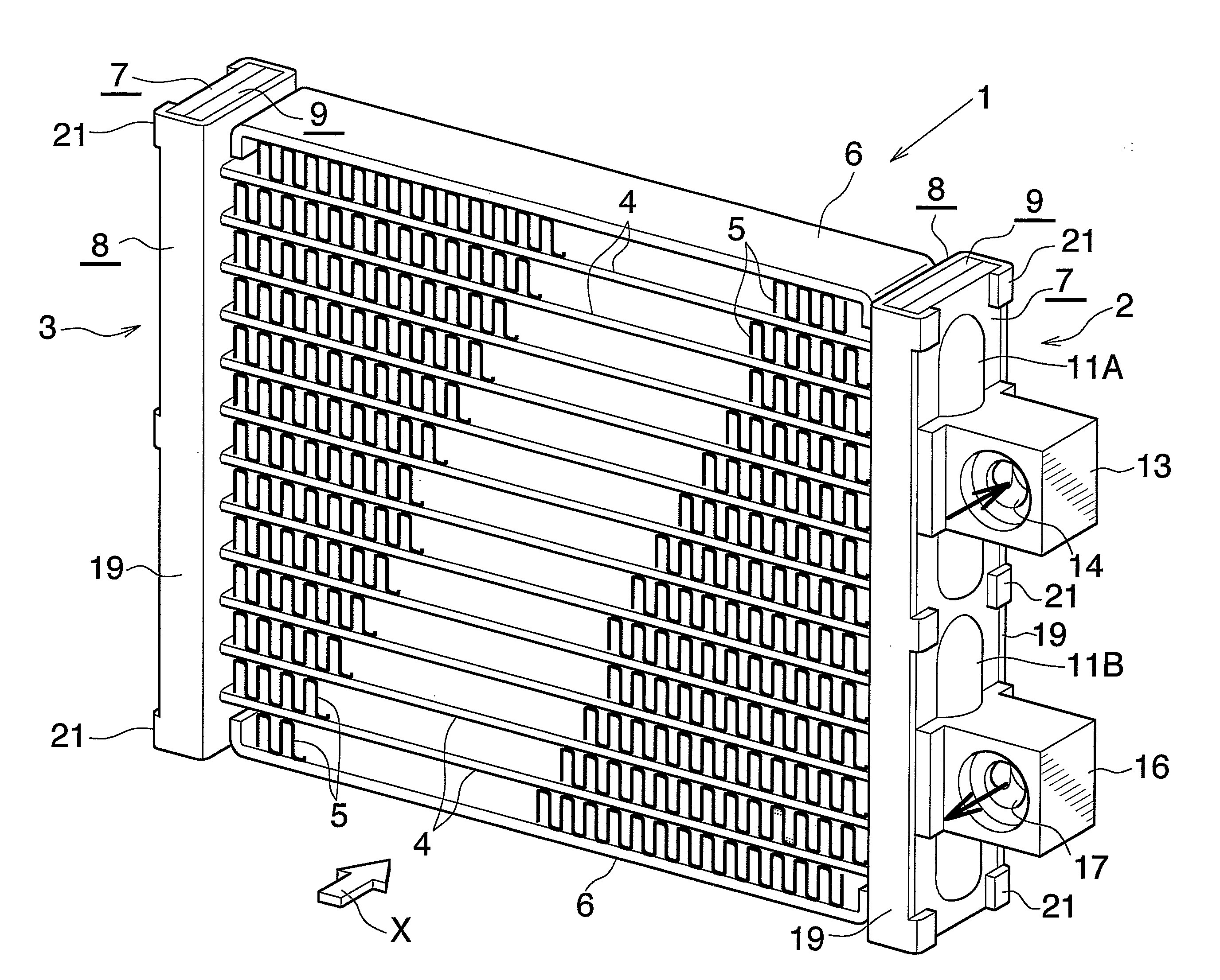
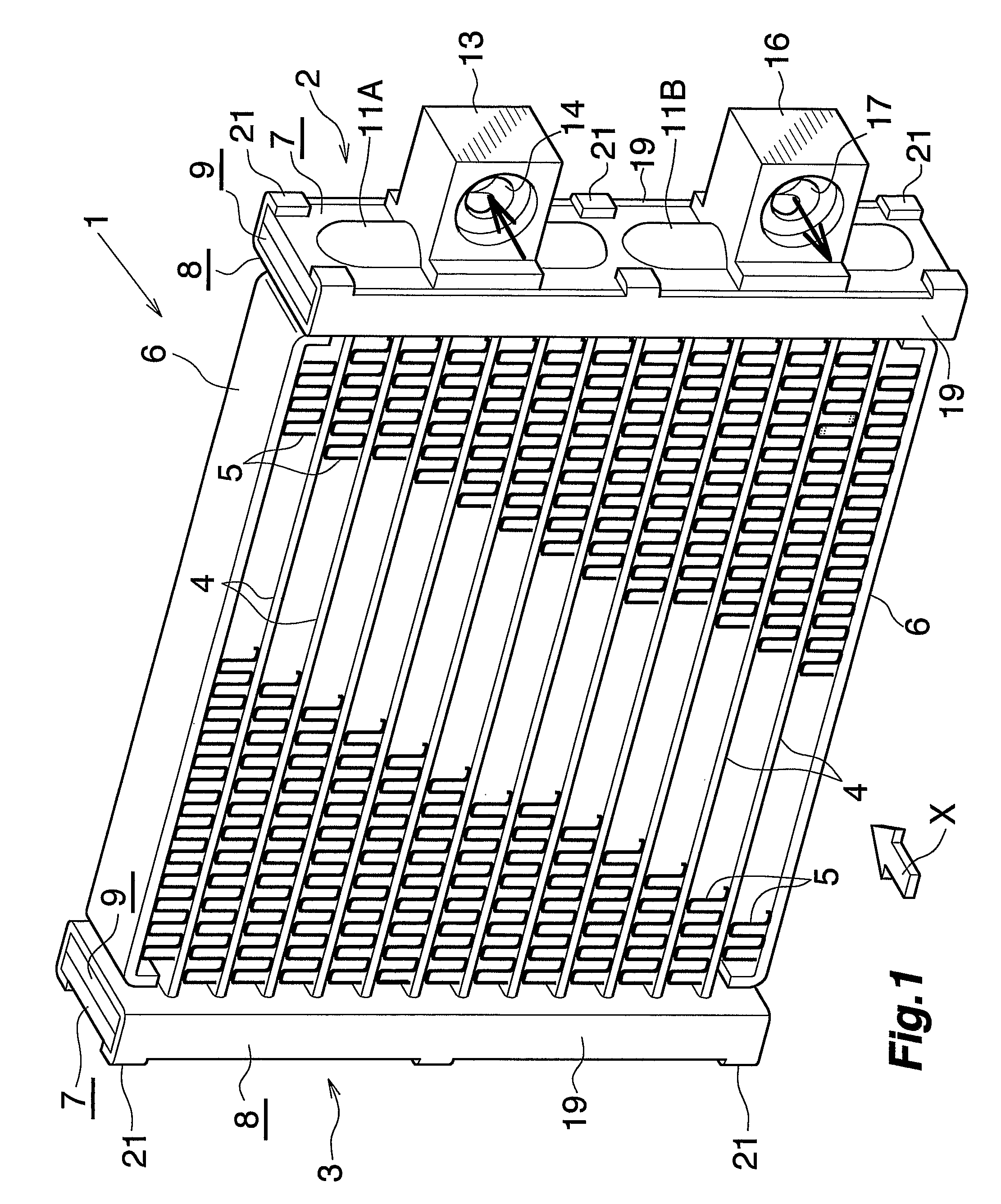
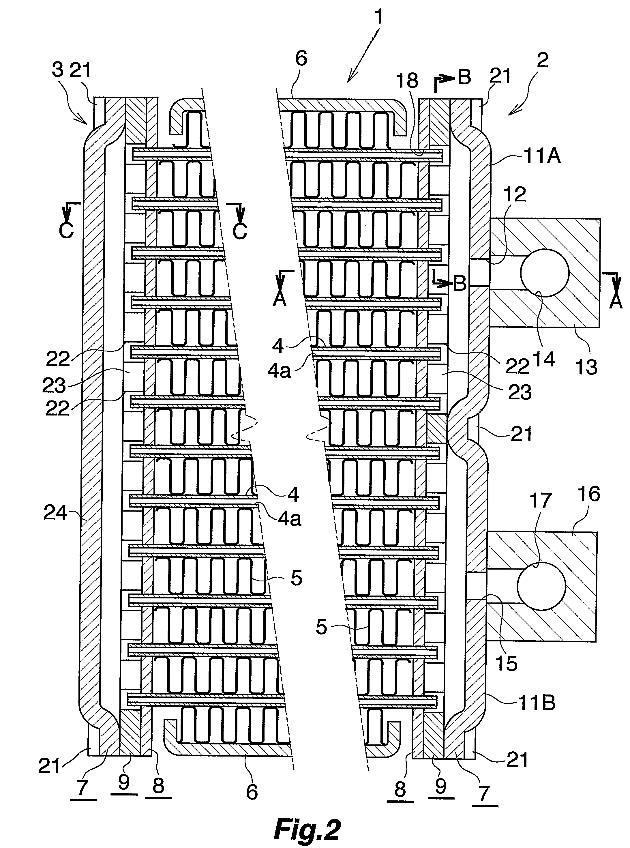
[0077]This embodiment is shown in FIGS. 1 to 9 and is a gas cooler for supercritical refrigeration cycles which comprises a heat exchanger of the present invention.

[0078]With reference to FIG. 1, the gas cooler 1 for use in supercritical refrigeration cycles wherein a supercritical refrigerant, such as CO2, is used comprises two header tanks 2, 3 extending upward or downward and arranged as spaced part in the left-right direction, a plurality of flat heat exchange tubes 4 arranged one above another at a spacing in parallel between the two header tanks 2, 3, corrugated fins 5 arranged in respective air passing clearances between respective adjacent pairs of heat exchange tubes 4 and outside the heat exchange tubes 4 at the upper and lower ends of the cooler and each brazed to the adjacent pair of heat exchange tubes 4 or to the end tube 4, and side plates 6 of bare aluminum material arranged externally of and brazed to the respective fins 5 at the upper and lower ends. In the case of...

embodiment 2

[0093]This embodiment is shown in FIGS. 10 to 20 and comprises a heat exchanger of the invention adapted for use as an evaporator in supercritical refrigeration cycles.

[0094]With reference to FIGS. 10 to 12, the evaporator 30 for use in supercritical refrigeration cycles wherein a supercritical refrigerant, such as CO2, is used comprises two header tanks 31, 32 extending in the left-right direction and arranged as spaced part in the upward or downward direction, a plurality of flat heat exchange tubes 33 arranged in parallel in the left-right direction at a spacing between the two header tanks 31, 32, corrugated fins 34 arranged in respective air passing clearances between respective adjacent pairs of heat exchange tubes 33 and outside the heat exchange tubes 33 at the left and right ends of the evaporator and each brazed to the adjacent pair of heat exchange tubes 33 or to the end tube 33, and side plates 35 of aluminum arranged externally of and brazed to the respective fins 34 at...


PUM

PropertyMeasurementUnit
heightaaaaaaaaaa
thicknessaaaaaaaaaa
heightaaaaaaaaaa

Abstract

A heat exchanger has header tanks each including a header forming plate, a tube connecting plate, and an intermediate plate interposed between the two plates, the plates being arranged in superposed layers and brazed to one another. Each of the plates is made from a metal plate by press work. The header forming plate has an outward bulging portion. The tube connecting plate has tube insertion holes. The intermediate plate has communication holes causing tube insertion holes to communicate with the interior of each outward bulging portion therethrough. Heat exchange tubes have opposite ends placed into the respective insertion holes and brazed to the respective tube connecting plates. The heat exchanger including such header tanks is reduced in the number of components, can be fabricated with a high work efficiency, and exhibits improved heat exchange performance.

Description

CROSS REFERENCE TO RELATED APPLICATION[0001]This application is an application filed under 35 U.S.C. §111(a) claiming the benefit pursuant to 35 U.S.C. §119(e)(1) of the filing dates of Provisional Applications No. 60 / 555,705 filed Mar. 24, 2004 and No. 60 / 655,426 filed Feb. 24, 2005 pursuant to 35 U.S.C. §111(b).TECHNICAL FIELD[0002]The present invention relates to heat exchanger header tanks and heat exchangers comprising the header tank, and more particularly to header tanks for use in heat exchangers, such as gas coolers or evaporators of supercritical refrigeration cycles wherein a CO2 (carbon dioxide) refrigerant or like supercritical refrigerant is used, and heat exchangers.[0003]The term “aluminum” as used herein and in the appended claims includes aluminum alloys in addition to pure aluminum.BACKGROUND ART[0004]Already known for use in supercritical refrigeration cycles is a heat exchanger comprising a pair of header tanks arranged as spaced apart from each other, heat exch...

Claims


Application Information

Patent Timeline
Patent Type & Authority Patents(United States)
IPC IPC(8): F25B39/02F25B1/00F25B39/00F25B39/04F28D1/053F28F9/02F28F9/04F28F21/08F28F27/02
CPCF25B39/00F28D1/05391F28F9/0204F28F9/0209F28F9/0246F28F9/0253F28F9/0278F25B39/02F25B2309/061F28D2021/0073Y10T29/49378F28D2021/0085
Inventor ICHIYANAGI, SHIGEHARU
Owner RESONAC HOLDINGS CORPORATION
Why Eureka
Try Eureka