
Fixed bed hypersorber and fractionation of fluids using the same

a technology of hypersorber and fixed bed, which is applied in the direction of cation exchanger, component separation, water/sludge/sewage treatment, etc., can solve the problems of poor recovery, sharp separation cannot be achieved, and the hypersorber as a separation process never gained popularity as a sound unit operation, etc., and achieve the effect of effective heat exchang

Active Publication Date: 2010-08-10
INDIAN INST OF TECH DEPT OF CHEM ENG INDIAN INST OF TECH +1
View PDF10 Cites 0 Cited by
  • Summary
  • Abstract
  • Description
  • Claims
  • Application Information

AI Technical Summary

Benefits of technology

[0013]Still another object of the present invention is to effectively fractionate any gas mixture into two product streams—the Raffinate product stream and the Extract product stream. One more object of the present invention is to effectively fractionate any gas mixture into two streams—the Raffinate stream and the Extract stream in four fixed beds using five steps that are staggered in between the beds in such a way the process is continuous.

Problems solved by technology

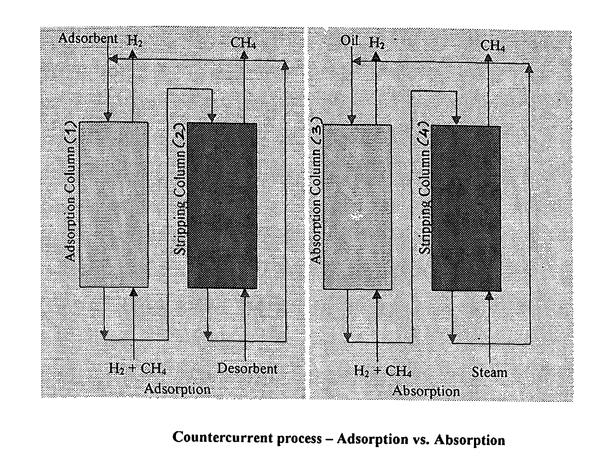
Hypersorption as a separation process never gained popularity as a sound unit operation to replace conventional operations due to the mechanical problems that persisted in solid handling, mainly the attrition and consequent loss of the by the adsorbents.
However, if the separation factor is between 1.5 and 10, sharp separation cannot be achieved.
We get one component to be nearly pure but the recovery is poor.
For example, separation of propylene (50 mol %) and propane (50 mol %) by PSA yields about 95% propylene, but the yield is low as low as 50%, which means the rest of propylene is lost with propane.
Unfortunately, due to problems of adsorbent attrition, liquid channeling and non-uniform flow of adsorbent particles; such a system has not been successfully developed.
However, the attendant mechanical complexity involved in handling of solids and the loss of adsorbent due to attrition have inhibited the use of the continuous countercurrent processes.
These problems are responsible for the demise of the hypersorption process.
Also, such fixed bed hypersorbers can stage process intensification of housing both the reaction as well as separation within a single bed.

Method used


Image

  • Fixed bed hypersorber and fractionation of fluids using the same
  • Fixed bed hypersorber and fractionation of fluids using the same
  • Fixed bed hypersorber and fractionation of fluids using the same

Examples


Embodiment Construction

[0037]Accordingly, the present application provides a fixed bed hypersorber effectuating countercurrent solid-gas / solid-liquid contacting, said hypersorber comprising:[0038]a column comprising solid absorbent / adsorbent material in the form of packed bed section, and

one or more moving port fluid injection and withdrawal systems incorporated inside the column for injecting and withdrawing the gas / liquid to be purified.

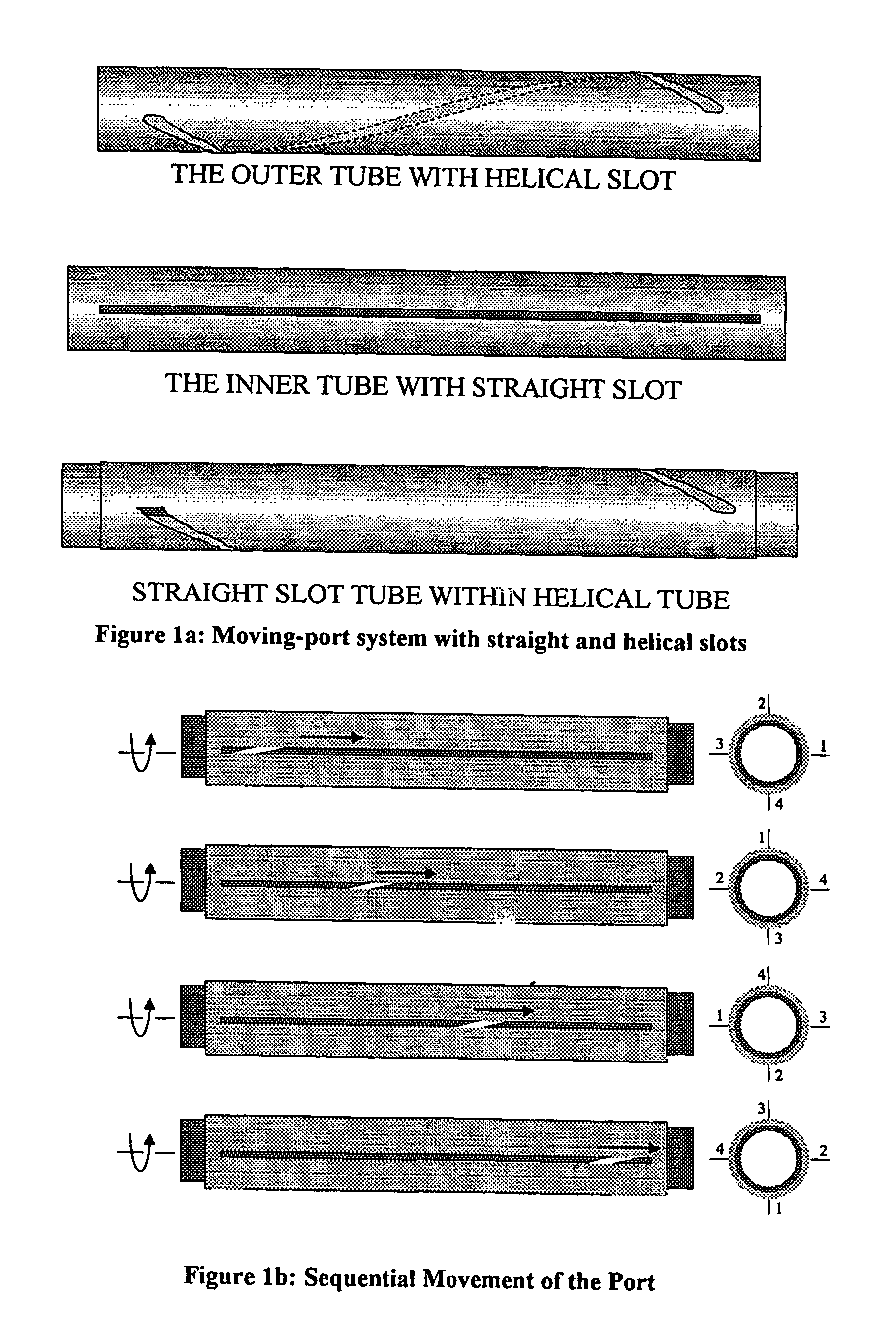
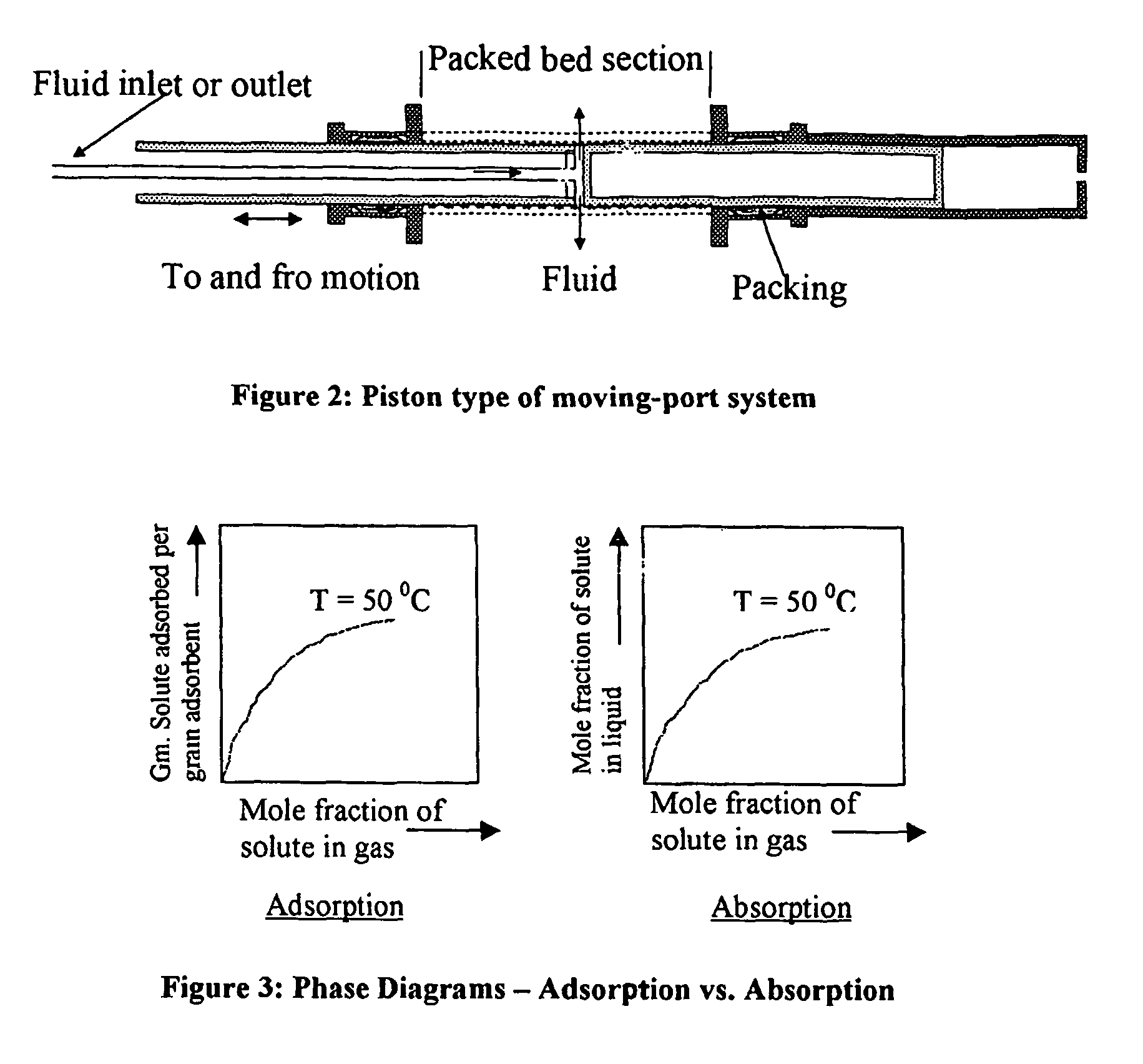
[0039]In an embodiment of the present application, the moving port fluid injection and withdrawal system comprises of conduit or piston moving in to and fro direction through the column comprising the solid absorbent / adsorbent.

[0040]In another embodiment of the invention, the moving port fluid injection and withdrawal system comprises of a pair of tube arranged in a concentric fashion, wherein one of the tubes is provided with a straight slot and the other tube is provided with a helical slot, and both the tubes are rotated with respect to each other by means of a motor....


PUM

PropertyMeasurementUnit
circumferenceaaaaaaaaaa
pressureaaaaaaaaaa
movementaaaaaaaaaa

Abstract

The present invention relates to a fixed bed hypersorber having moving ports for injecting and withdrawing fluids which can be used for fractionation of gaseous mixtures in a fixed bed filled with absorbents / adsorbents, where separation is brought about by contacting gaseous mixture in a counter-current fashion. The moving ports may take the form of pistons or pairs of tubes arranged concentrically, where one of the tubes has a straight slot and the other tube has a helical slot. Rotation of the tubes with respect to each other produces the moving port.

Description

TECHNICAL FIELD[0001]The present invention relates to a fixed bed hypersorber having moving ports for injecting and withdrawing fluids. The improved fixed bed hypersorber of the present invention can be used for fractionation of gaseous mixtures in fixed beds filled with adsorbent unlike that in a conventional Hypersorber, where separation is brought about by contacting the gas mixtures in a countercurrent manner with moving adsorbent. The said moving port system effectuates countercurrent solid-gas / solid-liquid contact in a fixed bed. More particularly, the present invention is directed towards two alternate methods of injection and withdrawal of fluids through moving ports—one with the concept of a moving port with helical slots, and the other being a piston type moving port system. The process of contacting the solid-gas / solid-liquid in a countercurrent fashion to emulate a hypersorber in fixed beds is effectuated in the present application either by the moving ports, or by a seq...

Claims


Application Information

Patent Timeline
Patent Type & Authority Patents(United States)
IPC IPC(8): B01D53/02B01D15/18B01D15/22B01D53/04G01N30/42G01N30/60
CPCB01D15/1807B01D15/22B01D53/0446B01D53/047G01N30/42G01N30/606B01D53/04B01D53/0423B01D2253/102B01D2253/104B01D2253/108B01D2253/25B01D2256/16B01D2257/7025B01D2259/40005B01D2259/402B01D2259/403B01D2259/404Y02C20/20
Inventor RAMAPRASAD, BOJANKI SATYA GOVINDARAO, DAVULURI PRAHLADA
Owner INDIAN INST OF TECH DEPT OF CHEM ENG INDIAN INST OF TECH
Learn More