
Mounting bracket for electrical junction box, luminaire or the like

a technology for mounting brackets and junction boxes, applied in fixed installation, transportation and packaging, light and heating equipment, etc., can solve the problems of inability to reliably attach temporary attachments, awkward installation of typical new work fixtures in ceilings,

Inactive Publication Date: 2010-08-10
GOODE JOHN A
View PDF4 Cites 62 Cited by
  • Summary
  • Abstract
  • Description
  • Claims
  • Application Information

AI Technical Summary

Problems solved by technology

Installing a typical new work fixture in a ceiling is often awkward and sometimes hazardous, because the operation requires an installer to hold the fixture up against a structural member, typically over head, while the installer drives one or more fasteners, such as screws or nails, through a portion of the fixture, such as a bracket, into the structural member.
However, such temporary attachments are not reliable, particularly when used overhead.

Method used


Image

  • Mounting bracket for electrical junction box, luminaire or the like
  • Mounting bracket for electrical junction box, luminaire or the like
  • Mounting bracket for electrical junction box, luminaire or the like

Examples


Embodiment Construction

[0027]In accordance with embodiments of the present invention, electrical fixtures are disclosed that support themselves while fasteners are driven to secure the fixtures to structural members. As used herein, the term “fixture” includes electrical junction boxes, luminaires (such as recessed “light cans”), ceiling-mounted electric radiant infrared heaters, fans and the like.

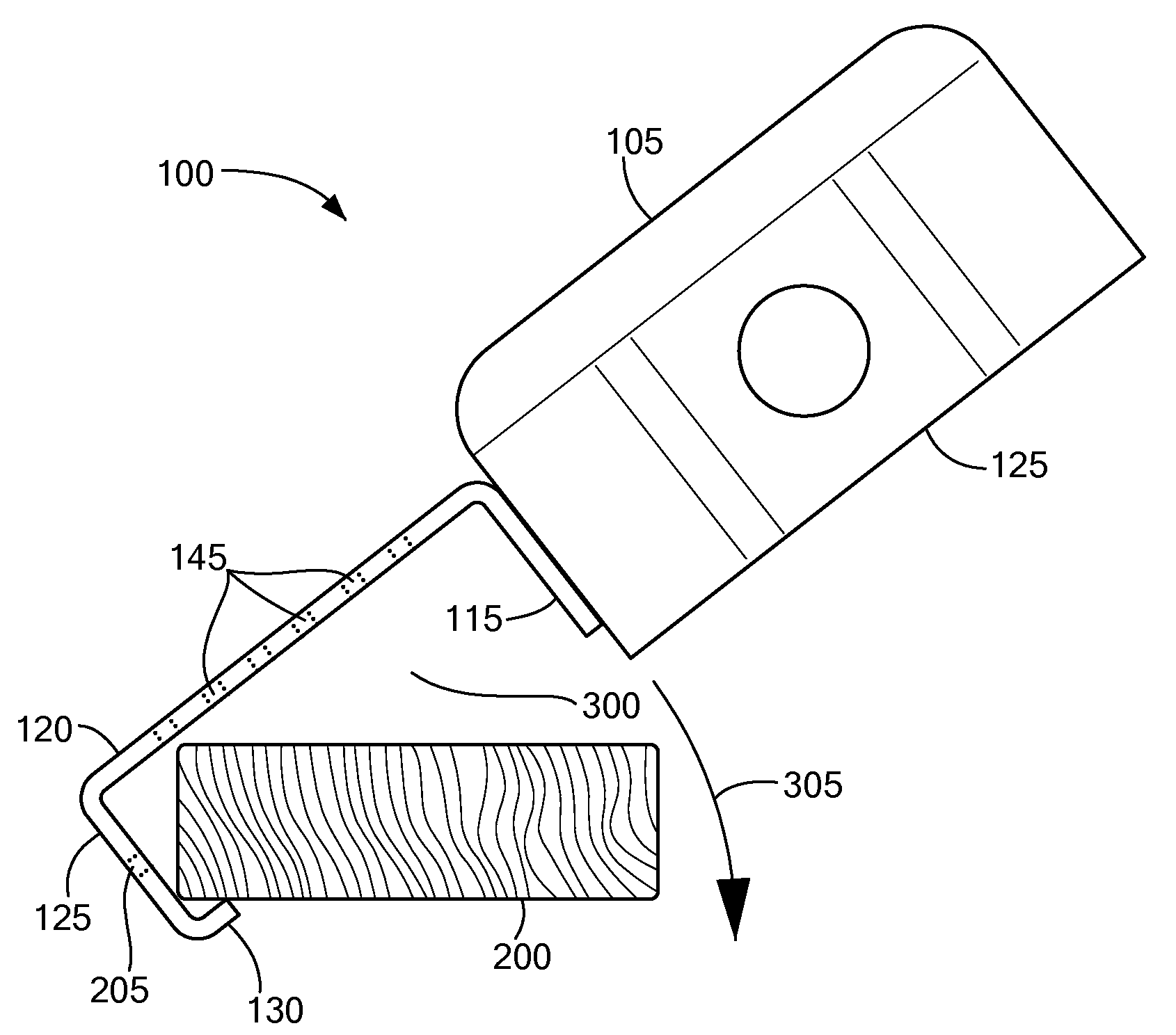
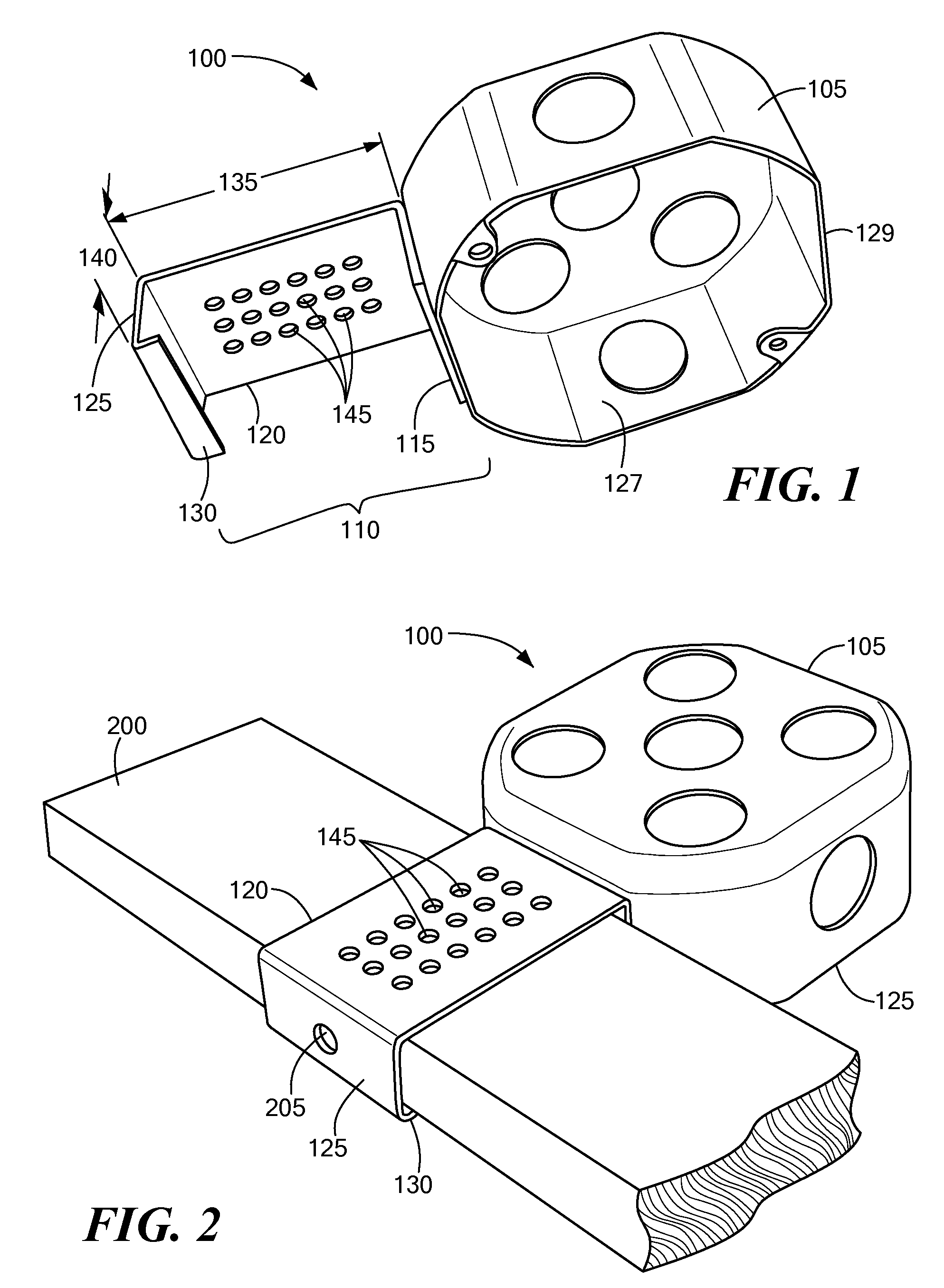
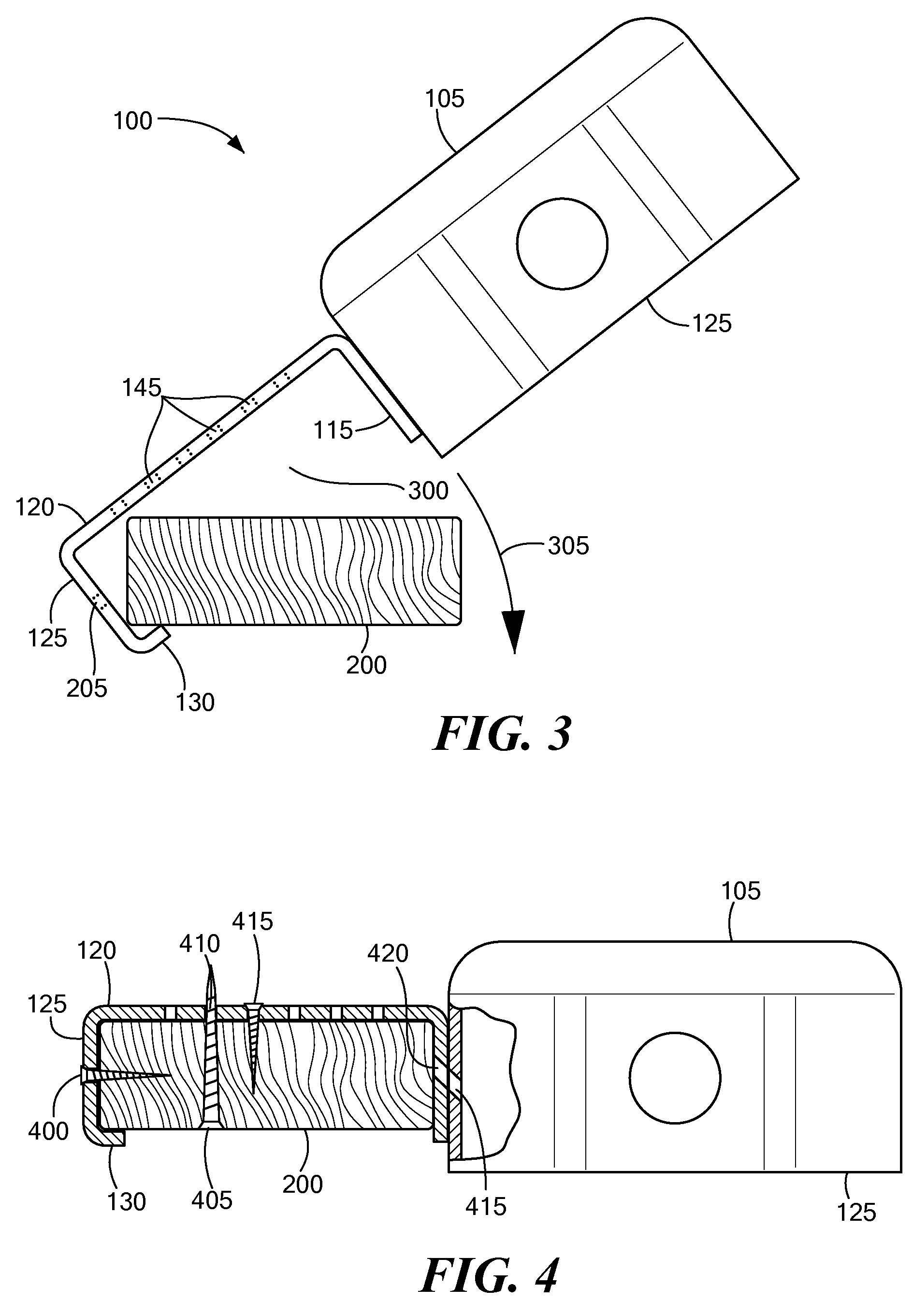
[0028]FIG. 1 is a perspective view (from below and to one side) of an electrical fixture 100 that includes a junction box 105 with an integral or attached mounting bracket 110, according to one embodiment of the present invention. FIG. 2 is a perspective view (from above and to one side) of the fixture 100 attached to a wood furring strip 200, although with modifications to the mounting bracket 110, the fixture 100 may be mounted to other types or sizes of structural members, such as metal furring strips or wood or metal joists, as described below. FIG. 3 is a side view of the fixture 100 being attached to the f...


PUM


Abstract

Electrical fixtures, such as junction boxes or recessed luminaires, include mounting brackets that support the fixtures from structural members while fasteners, such as screws or nails, are driven through the mounting brackets, thereby facilitating mounting the fixtures. Each of the mounting brackets has a general U-shape that includes at least three generally planar sides. The top side is generally perpendicular to the other two sides, and the top side connects the other two sides and together. The three sides define (in cross-section) a structural member receiver opening. An inside dimension of the structural member receiver opening is such that bracket fits snugly around at least a portion of a commonly sized wood or metal structural member, such as a furring strip or joist, used in ceiling construction. In one embodiment, two of the sides of the structural member receiver opening define an acute dihedral angle to hood around the edge of a metal furring strip.

Description

TECHNICAL FIELD[0001]The present invention relates to mounting brackets for electrical junction boxes, luminaires, etc. and, more particularly, to mounting brackets that support these types of fixtures, such as while fasteners are inserted to secure the brackets to structural members.BACKGROUND ART[0002]Installations of electrical junction boxes, recessed lighting fixtures, other types of luminaires or other types of electrical fixtures are commonly classified as “new work” or “old work” depending on how the fixtures are mounted. “Old work” refers to the use of existing plaster board or other surface material to support the fixtures. “New work” refers to the use of structural members, such as wood or metal joists or furring strips, to support the fixtures.[0003]Installing a typical new work fixture in a ceiling is often awkward and sometimes hazardous, because the operation requires an installer to hold the fixture up against a structural member, typically over head, while the insta...

Claims


Application Information

Patent Timeline
Patent Type & Authority Patents(United States)
IPC IPC(8): F21V15/00
CPCH02G3/126H02G3/20
Inventor GOODE, JOHN A.
Owner GOODE JOHN A
Learn More