
Differential pressure measurement device having a microwave resonator with a flexible member

a technology of differential pressure measurement and flexible member, which is applied in the direction of differential pressure measurement, volume/mass flow by dynamic fluid flow effect, liquid/fluent solid measurement, etc., which can solve the problems of interference with the desired measurement, prone to drift of measurement of typical inductance, capacitance and resistance values

Inactive Publication Date: 2010-08-10
ROXAR FLOW MEASUREMENT
View PDF13 Cites 20 Cited by
  • Summary
  • Abstract
  • Description
  • Claims
  • Application Information

AI Technical Summary

Benefits of technology

The patent describes a device for measuring differential pressure (dP) in a fluid flow. The device includes a microwave resonator with a flexible or yieldable part that can deform when exposed to dP. The microwave resonator has a resonant frequency that changes when exposed to dP. The device can be integrated into a pipeline to measure dP at various locations. The device can also include a single or double microwave probe for exciting and detecting the microwave signal. The device can be controlled and processed using software and hardware programming. The technical effects of the invention include improved accuracy and reliability in measuring dP in fluid flow and the ability to measure dP at multiple locations in a pipeline.

Problems solved by technology

The prior art has some limitations.
Measurements of typical inductance, capacitance and resistance values are prone to drift, e.g. with temperature of the electronics, unless properly compensated.
Contributions to the measured capacitance from lengthy wires and other parts of the measurement circuitry may interfere with the desired measurement.
First, prior art dP-units qualified for subsea use are relatively expensive and relatively bulky, and they add to the total amount of electronics in a flow metering installation.
Secondly, when used in the oil and gas industry for transporting fluid mixtures of liquid and gaseous hydrocarbons and possibly water, a dP-transmitter is normally connected to pressure taps via a pipe or duct section of some length.
Such pipe or duct sections are prone to clogging, e.g. by hydrate formation due to a higher temperature inside the transporting conduit than in the pipes leading to the dP-transmitter.

Method used


Image

  • Differential pressure measurement device having a microwave resonator with a flexible member
  • Differential pressure measurement device having a microwave resonator with a flexible member
  • Differential pressure measurement device having a microwave resonator with a flexible member

Examples


Embodiment Construction

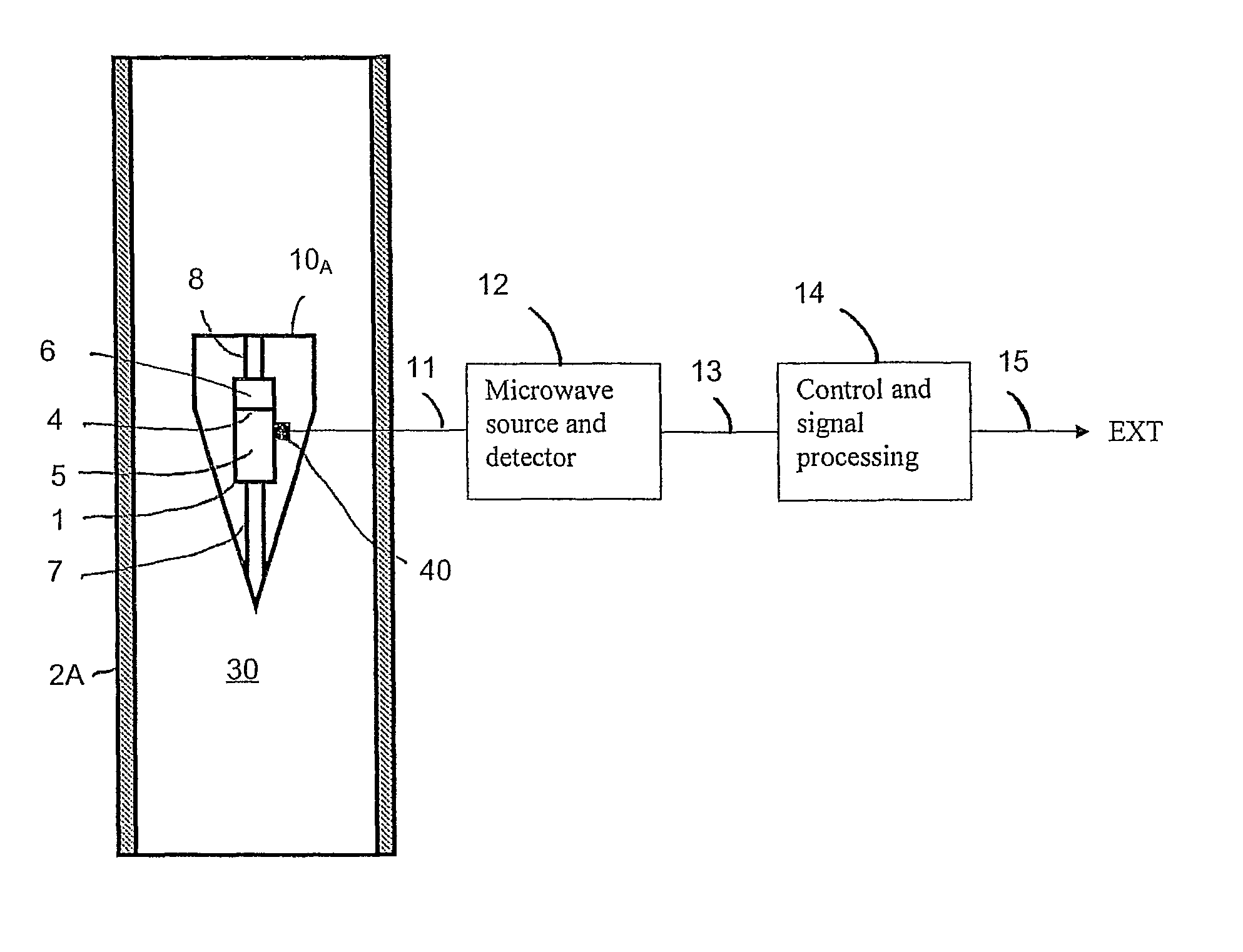
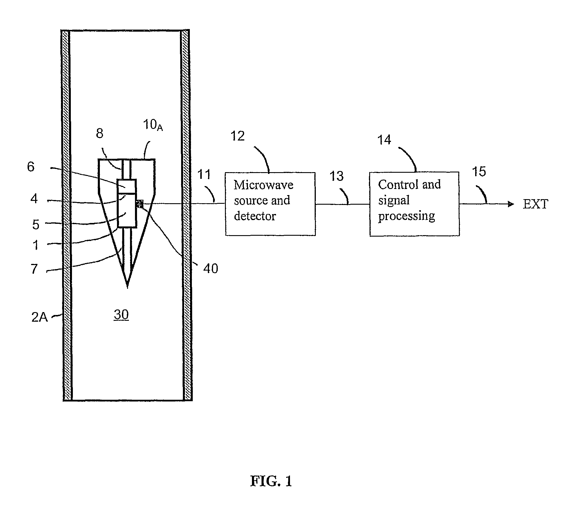
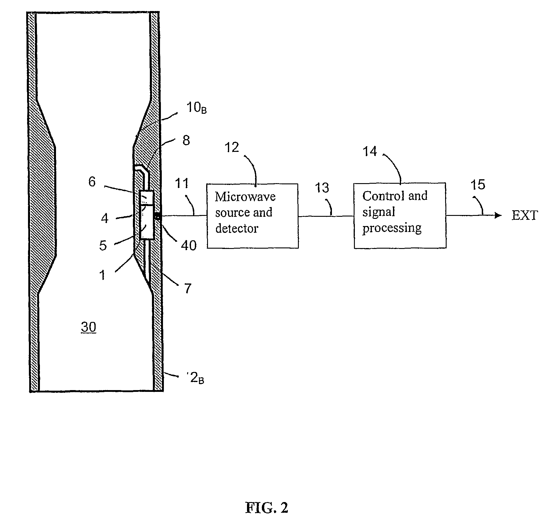
[0048]FIG. 1 illustrates one example embodiment of a differential pressure (dP) measurement device for use in flow measurement wherein a differential pressure sensitive microwave resonator 1 has a flexible or yieldable part or member 4 which deforms or yields when subject to a differential pressure. In this way the microwave resonant frequency of the resonator changes when the dP-measurement device is subjected to a differential pressure. In FIG. 1 the microwave resonator with the flexible or yieldable membrane is integrated in a differential pressure generating structure 10A having a shape resembling a V-cone. The differential pressure generating structure 10A is mounted inside a pipeline 2A, whereby a fluid volume 30 flowing past the differential pressure generating structure 10A creates a pressure differential between an upstream end and a downstream end of the differential pressure generating structure 10A. The flexible or yieldable part or member 4 in this case is a membrane wh...


PUM


Abstract

A differential pressure (dP) measurement device for use in flow measurement including a first microwave resonator (1) having a flexible or yieldable part or member (4) deformable or yieldable when subject to a differential pressure in such a way as to alter a resonant frequency of said resonator, and an electronic unit (12, 14) which is coupled to the resonator (1), and where the electronic unit is adapted to produce an output depending on a resonant frequency of the resonator (1).

Description

[0001]This application is the U.S. national phase of International Application No. PCT / NO2007 / 000032, filed 1 Feb. 2007, which designated the U.S. and claims priority to Norway Application No. 2006 0571, filed 3 Feb. 2006, the entire contents of each of which are hereby incorporated by reference.[0002]The present invention relates in general to flow metering and flow metering related to measurements in industrial applications in particular, for example measurements of two-phase or three-phase gas / hydrocarbon / water fluid flows in pipelines used in the oil and gas industry.[0003]More particularly, the present invention relates to a new device for making differential pressure measurements in a fluid flow, either in a stand-alone pressure sensor unit or for integration or combination with other types of sensors, such as e.g. sensors for permittivity, temperature, static pressure, etc.BACKGROUND AND PRIOR ART[0004]A common principle for the measurement of fluid flow is the measurement of...

Claims


Application Information

Patent Timeline
Patent Type & Authority Patents(United States)
IPC IPC(8): G01F1/34G01F15/075G01F1/37
CPCG01F1/363G01F1/40G01L13/06
Inventor NYFORS, EBBE GUSTAFSORENSEN, PER HASSEL
Owner ROXAR FLOW MEASUREMENT
Learn More