Fluid pump, cooling apparatus and electrical appliance

a technology of electrical appliances and pumps, applied in the direction of positive displacement liquid engines, pumping, liquid fuel engines, etc., can solve the problems of significant noise, generate considerable vibration, and the problem of vibration and noise is critical to be overcome, so as to achieve the effect of reducing vibration and nois

Inactive Publication Date: 2010-08-03
KK TOSHIBA
View PDF9 Cites 2 Cited by
  • Summary
  • Abstract
  • Description
  • Claims
  • Application Information

AI Technical Summary

Benefits of technology

[0010]Therefore, an object of the present invention is to provide a fluid pump that can minimize vibration and noise.
[0012]With the fluid pump thus configured, when the motor rotates the impeller to operate the pump, the fluid pressed by the pump vanes of the impeller collides with the pressure generating protrusion, thereby causing a portion of the fluid inside the pump chamber to be discharged through the discharge port. At this moment, since the lateral portion of the pressure generating protrusion on the discharge port side is formed in a smooth slope or curved surface, the impact created by the collision of the fluid with the pressure generating protrusion is mitigated. Accordingly, the vibration generated by the collision of the fluid with the pressure generating protrusion can be reduced, which also results in reduction of the noise accompanying the vibration.

Problems solved by technology

However, an existing fluid pump has a drawback that relatively strong vibration is generated during the pump operation (during the motor rotation), accompanied with a significant noise.
When the motor rotates the impeller for operating the pump, the fluid pressed by the pump vanes of the impeller collides with the pressure generating protrusion, which generates considerable vibration.
In particular, when such a fluid pump is employed in an electrical appliance, for example, for cooling a CPU in a personal computer, the vibration and noise are critical issues to be overcome.

Method used


Image

  • Fluid pump, cooling apparatus and electrical appliance
  • Fluid pump, cooling apparatus and electrical appliance
  • Fluid pump, cooling apparatus and electrical appliance

Examples


first embodiment

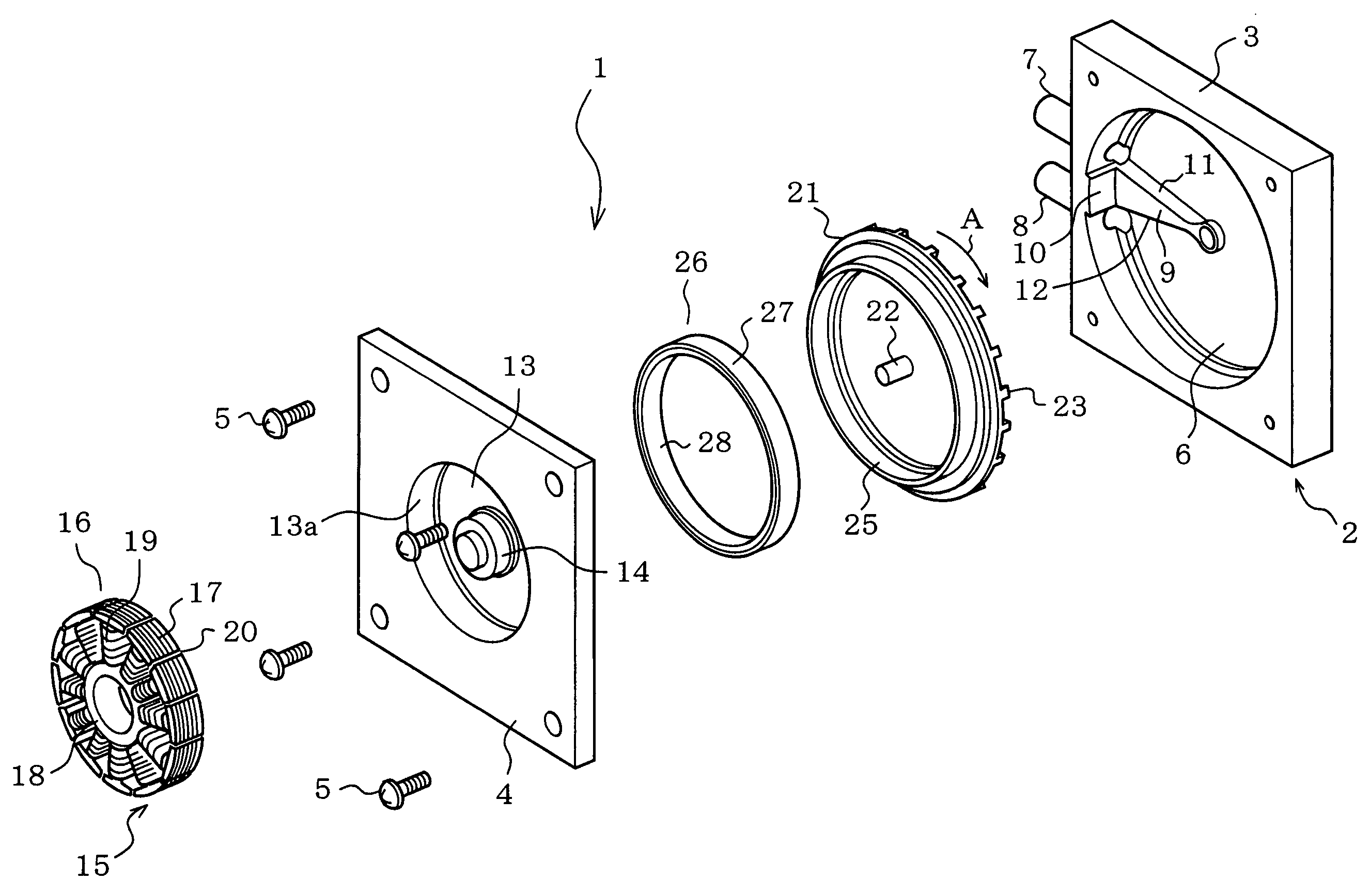
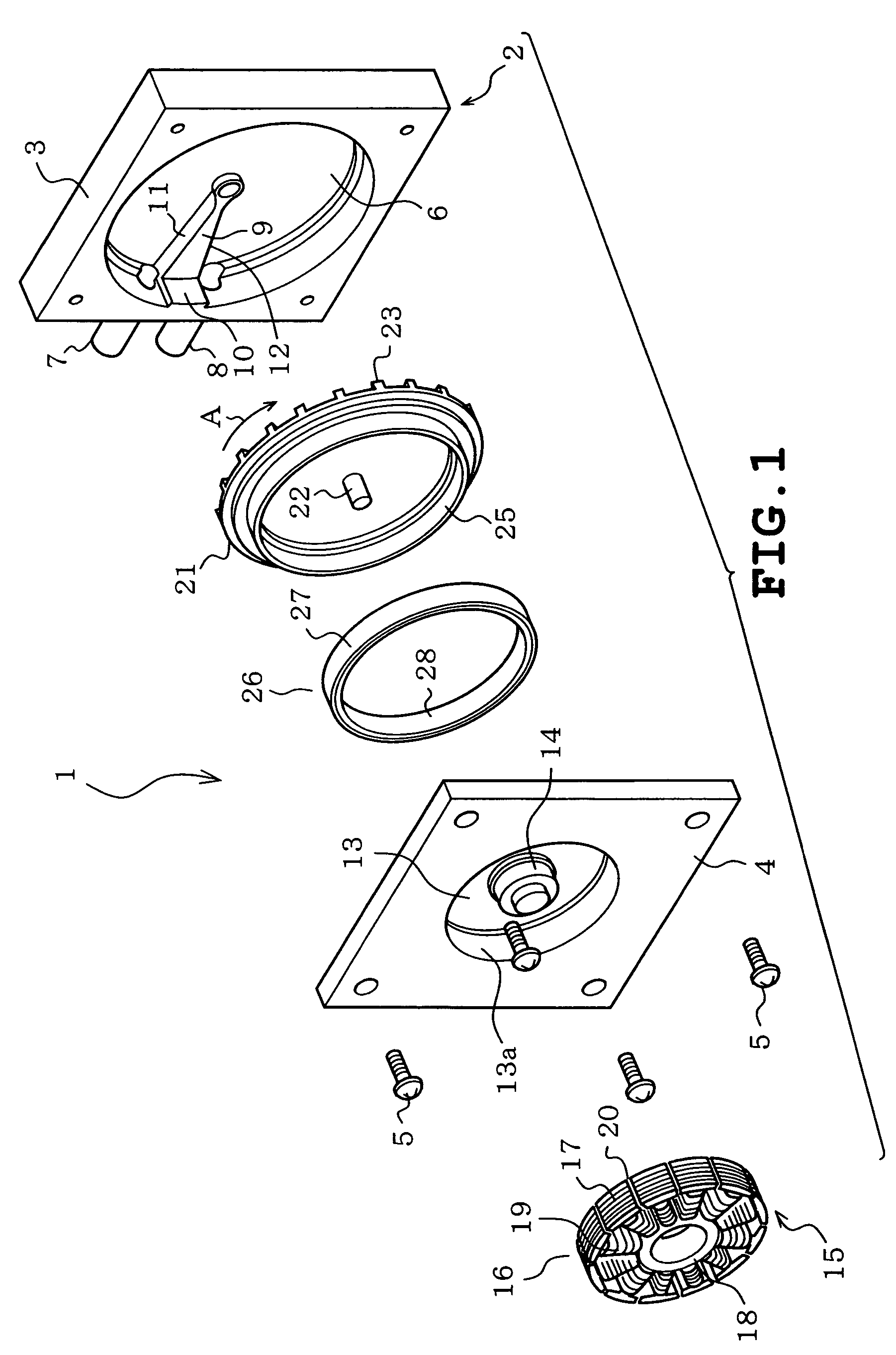
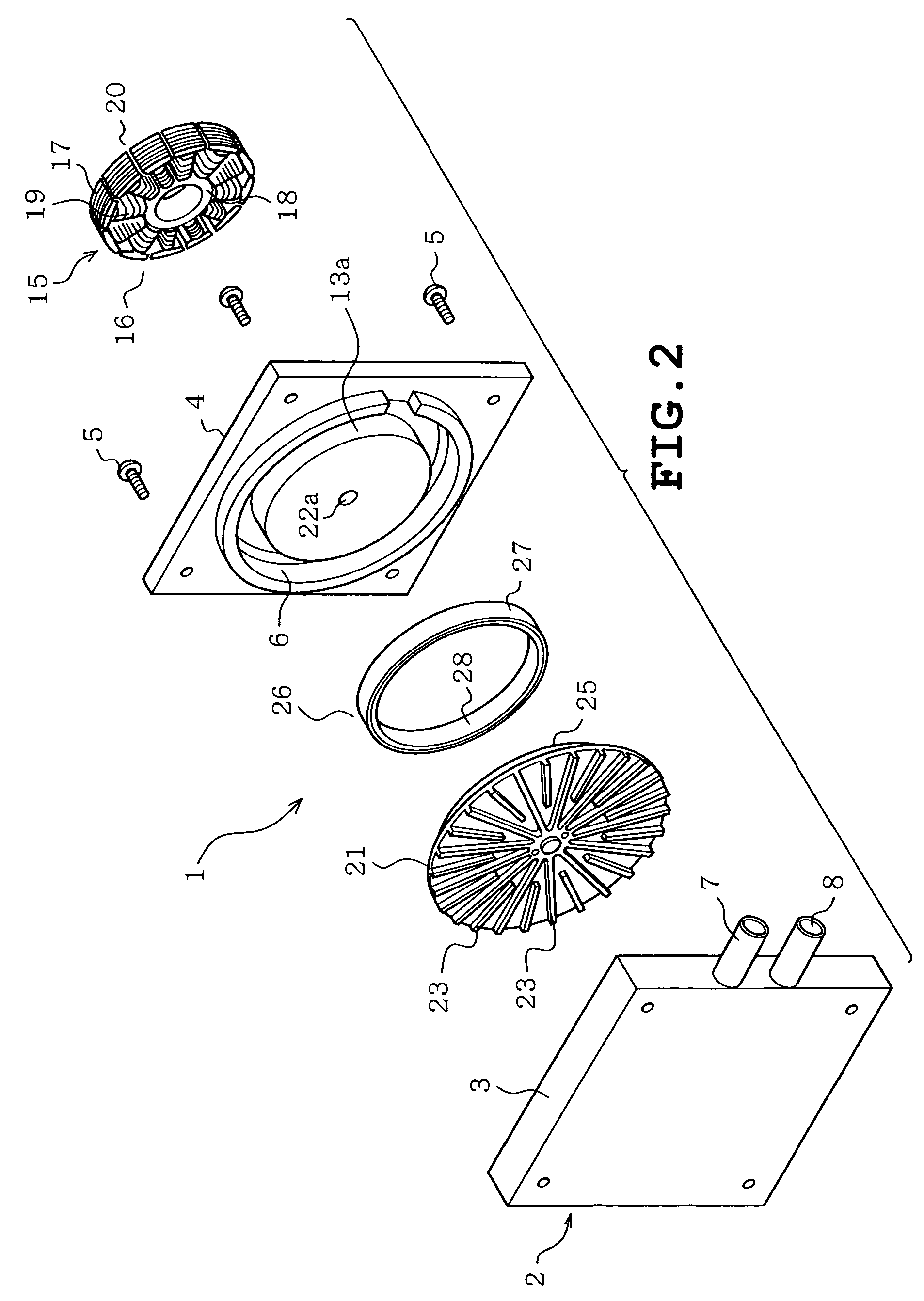
[0038]The first embodiment provides the following advantageous effects. First, referring to the fluid pump 1, since the lateral face of the radially extending first pressure generating protrusion 9, out of the first and the second pressure generating protrusions 9 and 10, is formed in a smooth slope 12 at least on the side of the discharge port 8, the fluid propelled by the pump vanes 23 when the impeller 21 rotates can flow relatively smoothly upon colliding with the first pressure generating protrusions 9, and hence the impact is mitigated. Accordingly the vibration generated by the collision of the fluid with the first pressure generating protrusion 9 can be reduced, which also results in reduction of the noise accompanying the vibration. In this embodiment, the lateral face of the first pressure generating protrusion 9 on the side of the suction port 7 is also formed in a smooth slope 11, the fluid can also flow through this region smoothly, which further reduces the vibration, ...

second embodiment

[0049] employing the fluid pump 1 constructed so as to suppress vibration and noise for use with the cooling apparatus 45 incorporated in the personal computer 46 achieves the personal computer 46 that suppresses vibration or noise.

[0050]FIGS. 10 and 11 depict a third embodiment of the present invention, which is different from the first embodiment in the following aspect. Referring to FIG. 10, the impeller 21 includes first pump vanes 61 radially extending from a central portion thereof, and second pump vanes 62 radially extending from halfway, such that the total number of the first pump vanes 61 and the second pump vanes 62 becomes 21, which is an odd number.

[0051]More specifically, the first pump vanes 61 are arranged at 7 positions, between which two each of the second pump vanes 62 are arranged. An angle θ1 between a first pump vane 61 and an adjacent second pump vane 62, and an angle θ2 between two second pump vanes 62 arranged next to each other are different (θ1>θ2). Accord...

third embodiment

[0053]The third embodiment provides the following advantageous effects. Since the total number of the first and the second pump vanes 61 and 62 of the impeller 21 is set to be 21, the impeller 21 generates a pressure 21 times per rotation. On the other hand as for the motor 15, since the rotor magnet 28 has 8 magnetic poles and the stator 16 has 12 slots, the rotor 26 generates a cogging torque 24 times per rotation, which is the lowest common multiple thereof. Therefore, the pressure generating frequency by rotation of the impeller 21 and the cogging torque generating frequency of the motor 15 are different, which allows reduction in the vibration and noise.

[0054]Also, the total number of the first and the second pump vanes 61 and 62 of the impeller 21 is set to be 21, which is an odd number. On the other hand, the motor 15 usually generates a cogging torque an even number of times per rotation of the rotor 26, for example, 24 times according to this embodiment, which is hence usua...


PUM


Abstract

A fluid pump having a case with a pump chamber defined by axial side surfaces and a circumferential surface, a suction port and a discharge port both provided in the circumferential surface so as to communicate with the pump chamber, an impeller formed into a disc shape and rotatably mounted in the pump chamber, a pressure generating protrusion, which generates pressure by rotation of the impeller and is located inside the pump chamber at a radial position, and a motor, which drives the impeller, installed in the case and having a stator and a rotor to which the impeller is attached for rotating together.

Description

CROSS REFERENCE TO RELATED APPLICATIONS[0001]This application is based upon and claims the benefit of priority from Japanese Patent Application No. 2004-099354, filed in Japan on Mar. 30, 2004.BACKGROUND OF THE INVENTION[0002]1. Field of the Invention[0003]The present invention relates to a fluid pump including a motor for rotationally driving an impeller, a cooling apparatus including such a fluid pump, and to an electrical appliance including such a cooling apparatus.[0004]2. Description of the Related Art[0005]A fluid pump is known which includes a motor having a rotor to which an impeller is integrally fixed for rotation together with the rotor, so that the pump vanes of the impeller serve to suction a fluid into a pump chamber via a suction port, and to discharge the fluid out of the pump chamber via a discharge port, as disclosed in Japanese Published Unexamined Patent Application No. 2001-123978 and Japanese Published Unexamined Patent Application No. 2001-132677, for example...

Claims


Application Information

Patent Timeline
Patent Type & Authority Patents(United States)
IPC IPC(8): F04B35/04F04B17/00F04B17/03F04D5/00F04D13/06F04D23/00F04D29/44F04D29/66
CPCF04D5/002F04D13/0673F04D29/669F04D29/666F04D29/667
Inventor SEKO, KATSUYAITO, KENICHI
Owner KK TOSHIBA
Why Eureka
Try Eureka