
Two-way damper

a damper and two-way technology, applied in mechanical equipment, transportation and packaging, functional valve types, etc., can solve problems such as power consumption, damage to the pipeline, and the operation of various valves in the vent system located in the vault,

Active Publication Date: 2010-08-03
VAL MATIC VALVE & MFG
View PDF7 Cites 7 Cited by
  • Summary
  • Abstract
  • Description
  • Claims
  • Application Information

AI Technical Summary

Benefits of technology

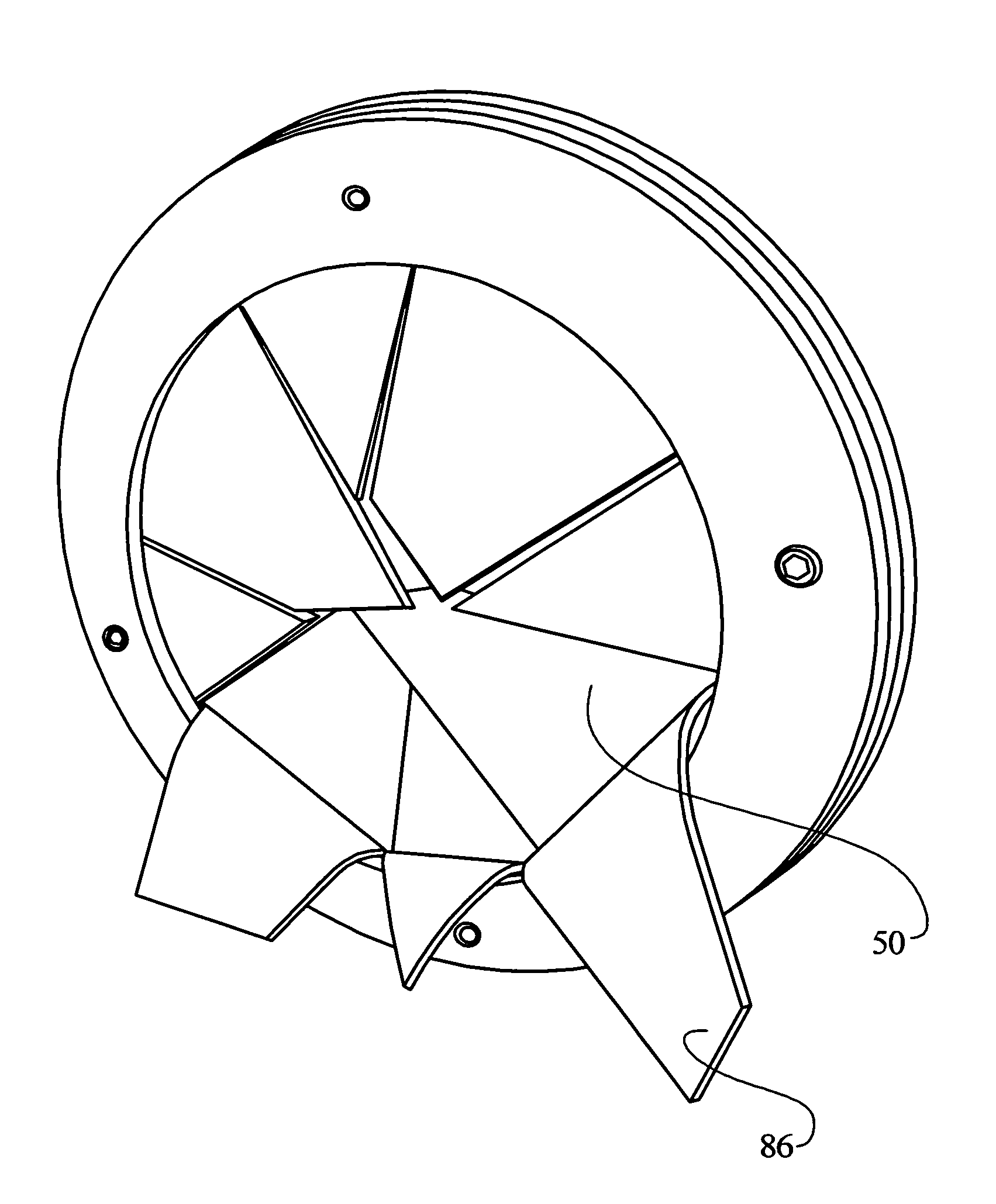
[0005]The present invention provides a two-way baffle for a vent pipe that will allow for gas flow in either direction when a pressure differential across the baffle is above a threshold pressure. The baffle will prevent the flow of gas when less than the threshold pressure differential exists across the baffle. The baffle also does not contain any rotating or pivoting parts, and so is not subject to having immobile parts in sub-freezing temperatures that would prevent operation of the baffle. The baffle may be oriented in a horizontal pipe, a vertical pipe, or in a pipe arranged at any other angle.
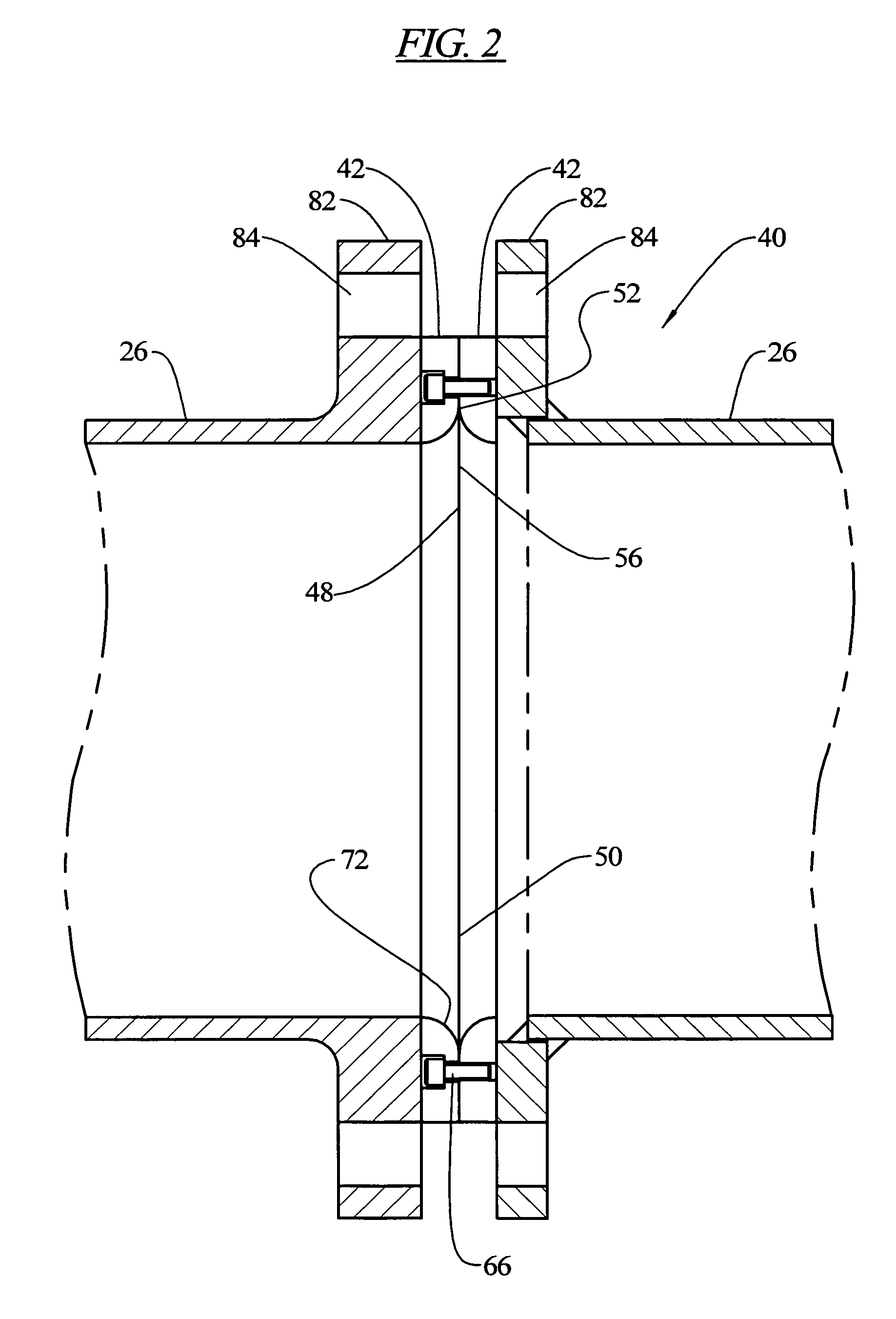
[0010]In an embodiment, a two-way damper comprising a combination of a baffle and a retaining member is provided, the baffle comprising a generally circular flexible member with a first portion, at a portion of a periphery of the member, secured and held in a fixed position by the retaining member, a second portion spaced from the retaining member normally oriented in a first position, but free to move relative to the first position, and a third portion, arranged between the first and second portions, being flexible and resilient. The third portion allows the second portion to move to a second position relative to the first position upon the application of a pressure differential across the baffle above a threshold pressure and causes the second portion to return to the first position upon the application of a pressure differential across the baffle below the threshold pressure.

Problems solved by technology

Although the pipes may be buried well below the frost line, if sub-freezing air flows into the vault due to the vault being vented, it is possible for the liquid in the pipeline to freeze, thereby damaging the pipeline.
Also, various valves utilized in the vent system and located in the vault may be subject to damage or operational deficiencies if frost or ice builds up on the valve components.
The motorized baffles require electricity to operate and may not have an open fail safe condition in the event of a power loss.
These weighted baffles also are typically pivotally mounted and thus suffer the same problems described above due to ice and frost build up.

Method used


Image

  • Two-way damper
  • Two-way damper
  • Two-way damper

Examples


Embodiment Construction

[0039]The present invention generally relates to a damper system which may be used in connection with exhausting and emitting air when installed in vent pipes of water and waste handling pipelines and / or piping systems. A primary function of such vent pipes is to prevent air and / or vacuum related problems within a liquid pipeline. The damper system includes a baffle to control or prevent the flow of gas through the vent pipe when a pressure differential across the baffle is below some predetermined threshold pressure, but to allow passage of gas, in either direction through the vent pipe when the pressure differential across the baffle is above the threshold pressure.

[0040]Referring now to FIG. 1, a general arrangement of a liquid transport system 20 utilizing the present invention is illustrated. The system 20 includes a portion that is positioned within a vault 22 that is buried below a surface grade 24. The vault 22 includes a vent pipe 26 to allow an inflow and outflow of air re...


PUM


Abstract

A two-way damper is provided including a retaining member and a baffle. The baffle comprises a flexible member with a first portion secured and held in a fixed position by the retaining member and a second portion normally oriented in a first position, but free to move relative to said first position. The baffle also comprises a third portion, arranged between the first and second portions, being flexible and resilient and allowing the second portion to move to a second position relative to the first position upon the application of a pressure differential across the baffle above a threshold pressure and causing the second portion to return to the first position upon the application of a pressure differential across the baffle below the threshold pressure.

Description

BACKGROUND OF THE INVENTION[0001]The present invention generally relates to venting, exhaustion and / or admission of air in piping systems. More specifically, the present invention relates to a damper system and a method for controlling the entrance and exhaust of air into and from a venting system of a pipeline or reservoir.[0002]Venting systems are used with pipelines to prevent vacuum conditions within a liquid pipeline, and to allow for exhaust or purging of gases from the liquid carried in the pipeline. In the case of an underground pipeline, such as used with potable water systems or waste or ground water systems, oftentimes the vent connections occur in underground vaults and reservoirs, which themselves need to be vented to the atmosphere. Although the pipes may be buried well below the frost line, if sub-freezing air flows into the vault due to the vault being vented, it is possible for the liquid in the pipeline to freeze, thereby damaging the pipeline. Also, various valves...

Claims


Application Information

Patent Timeline
Patent Type & Authority Patents(United States)
IPC IPC(8): F16K15/14
CPCF16K15/144F16K15/147Y10T137/7881Y10T137/7885
Inventor MAKOWAN, TED J.O'SHEA, TIMOTHY M.
Owner VAL MATIC VALVE & MFG
Learn More